
Phasors: Rotating Vectors for Oscillating Quantities
For a resistor, v and i are in phase — but for inductors and capacitors they are not. To track phase relationships, we use phasors.
A phasor is a vector rotating counter-clockwise about the origin with angular speed . The vertical projection of the voltage phasor (length ) and current phasor (length ) at time t give the instantaneous values and . The angle between the phasors is the phase difference between v and i — frozen as both rotate together.
Key Point (NCERT footnote): voltage and current are not actually vectors — they are scalars. It just happens that harmonically varying scalars combine mathematically like the projections of rotating vectors, so phasors give us a familiar (vector-addition) rule for adding oscillating quantities. A favourite 'true/false' exam line!
For the resistor: and point the same way at every instant — phase difference zero.
AC Across a Pure Inductor
Connect to an inductor of self-inductance L (winding resistance negligible). Kirchhoff's loop rule with the back emf (Chapter 6):
Integrating (and dropping the constant — the current oscillates symmetrically about zero, so no steady component exists):
is the inductive reactance — it limits the current exactly as resistance does, has the dimension of resistance, and is measured in ohms. It is directly proportional to both L and the frequency.
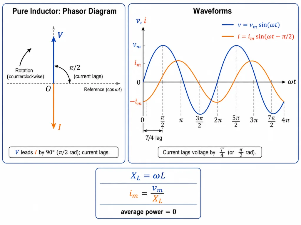
The headline: in a pure inductor, the current LAGS the voltage by — one quarter cycle (). The current phasor trails the voltage phasor by 90 degrees.
[NEET Important] Memory hook for both reactive elements: 'L lags, C leads' (for the current relative to voltage).
An Inductor Consumes No (Average) Power
The instantaneous power delivered to the inductor:
The average of over a complete cycle is zero, so
Physically: for a quarter cycle the source feeds energy into the inductor's magnetic field; in the next quarter the field returns it. The energy sloshes back and forth, never dissipating — the inductor limits current without consuming power (unlike a resistor).
[JEE Tip] has two instructive limits: for DC (), — an ideal inductor is a plain wire to steady current; at high frequency it chokes the current off. Frequency-dependence questions on (and , next section) are near-guaranteed in JEE Main and NEET.
Solved Examples
Example 1: The 25 mH inductor (NCERT Example 7.2)
A pure inductor of 25.0 mH is connected to a 220 V, 50 Hz source. Find the inductive reactance and the rms current.
Solution:
- Reactance: .
- Current: A.
- A mere 7.85 ohm of reactance — yet no heat is generated in this ideal inductor.
Example 2: Reactance scales with frequency [NEET Numerical]
Find the reactance of a 0.1 H inductor at 50 Hz and at 500 Hz.
Solution:
- At 50 Hz: .
- At 500 Hz: ten times the frequency, ten times the reactance: .
- — a straight line through the origin on an vs graph.
Example 3: Writing i(t) completely [JEE Numerical]
A voltage V is applied to a pure 25 mH inductor. Write the full expression for the current.
Solution:
- .
- A.
- Current lags by : A.
Example 4: Lag in milliseconds [NEET Numerical]
On the 50 Hz mains, by how much time does the current in a pure inductor reach its peak after the voltage peaks?
Solution:
- The lag is a quarter cycle: .
- ms.
- Answer: ms — the current peaks 5 ms after the voltage, every cycle.
Example 5: Energy sloshing, quantified [JEE Numerical]
A 50 mH inductor carries an AC current of peak value 2.0 A. Find the maximum energy stored in it, and the average power it consumes.
Solution:
- Max stored energy: J — held momentarily at each current peak.
- Average power: zero — the same 0.1 J is returned to the source every quarter cycle.
- Energy circulates; nothing burns.
Example 6: The DC limit [JEE Numerical]
An ideal 0.2 H inductor is connected to (a) a 12 V DC battery, (b) a 12 V (rms), 50 Hz source. Compare the opposition it offers.
Solution:
- (a) DC: — an ideal inductor offers no opposition to steady current (real coils are limited only by their winding resistance).
- (b) AC: , so A.
- Same element, drastically different behaviour — reactance is a frequency phenomenon.
Example 7: Why does the current lag?
Explain physically why the current in an inductor lags the applied voltage.
Solution:
- An inductor's back emf opposes changes in current (Chapter 6 — electrical inertia).
- When the applied voltage is at its peak, it is still 'pushing the current up' against this inertia; the current reaches its own peak only a quarter cycle later.
- Mathematically the integration of gives — automatically a 90-degree lag.
Example 8: Phasors are not vectors
Voltage and current are represented by rotating vectors. Are they vector quantities? Justify.
Solution:
- No — voltage and current are scalars.
- Harmonically varying scalars happen to add with the same mathematics as projections of rotating vectors; phasors simply exploit that coincidence to give us an easy addition rule.
- NCERT flags this explicitly — quote it when asked, and earn the easiest mark of the paper.
Example 9: The iron rod and the bulb (NCERT Example 7.5)
A light bulb in series with an open-coil inductor glows on AC. An iron rod is inserted into the coil. What happens to the glow, and why?
Solution:
- The rod's iron is magnetised by the coil's field, greatly increasing the magnetic field inside — so the inductance L increases.
- rises, so a larger share of the source voltage drops across the inductor, leaving less for the bulb.
- The glow decreases. (Pull the rod out and it brightens again — induction made visible.)
Example 10: Where did the energy go?
Over one full cycle, the source connected to a pure inductor does zero net work — yet current flowed throughout. Reconcile.
Solution:
- During the quarter cycles when grows, the source feeds energy into the field ().
- During the quarter cycles when falls, the collapsing field drives the source backwards, returning that energy ().
- The ledger balances exactly each half cycle: . Current without consumption.