
All Three in Series: The Setup
Connect R, L and C in series to (NCERT Fig. 7.10). Kirchhoff's loop rule gives
We solve it with phasors. The crucial series-circuit fact: the same current flows through every element at every instant — same amplitude, same phase. Write it as
where is the phase of the current relative to the source voltage — the unknown we want, along with .
Each element's voltage phasor obeys its own rule from Sections 1-3:
- (length ): parallel to (in phase),
- (length ): 90 degrees ahead of ,
- (length ): 90 degrees behind .
Since and lie along the same line in opposite directions, they combine into a single phasor of magnitude .
Impedance and Phase Angle
The source phasor is the (vector) sum . With and the combined as the two perpendicular sides, Pythagoras gives
Z is the impedance (ohm) — the AC generalisation of resistance. The phase angle comes from the impedance triangle (sides R and , hypotenuse Z):
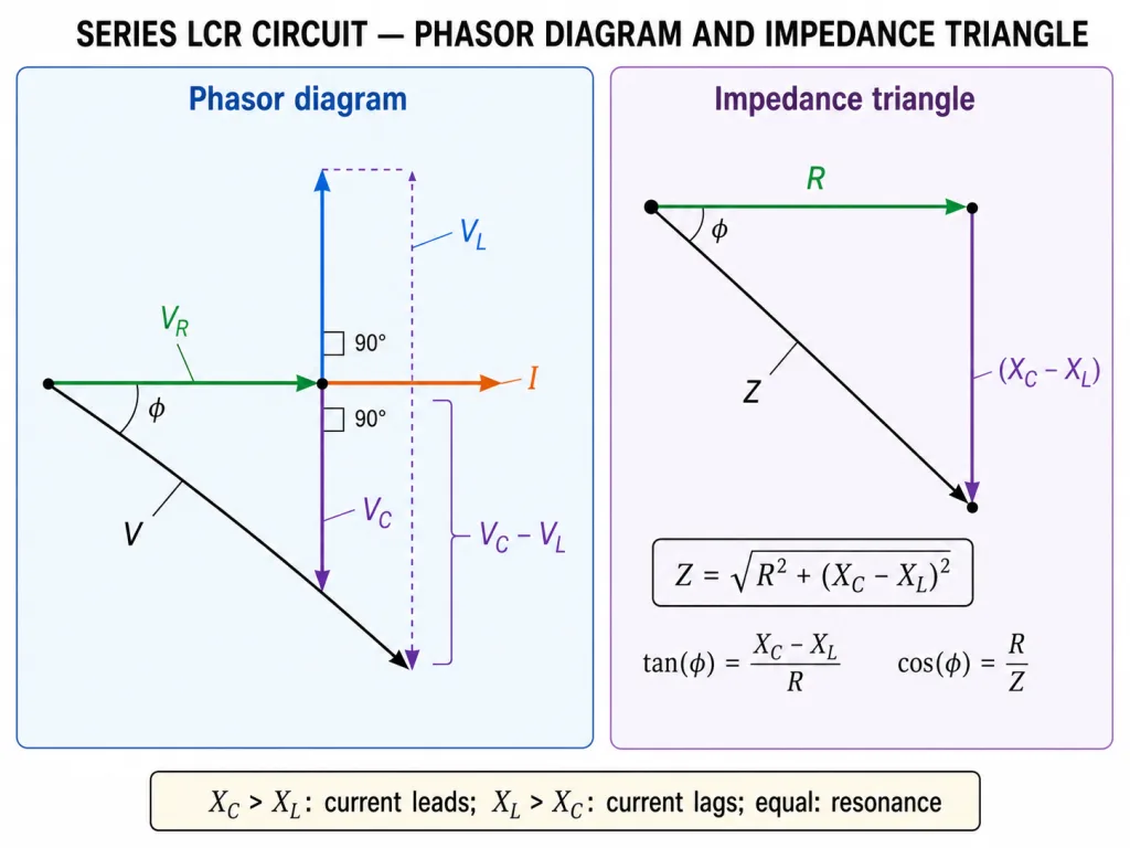
The three regimes:
| Condition | Circuit behaves | Current | |
|---|---|---|---|
| positive | capacitively | leads the voltage | |
| negative | inductively | lags the voltage | |
| zero | purely resistively | in phase (resonance!) |
The Voltage 'Paradox' and How to Read LCR Problems
A strange feature of series AC circuits: the rms voltages across the elements can algebraically add to MORE than the source voltage. Nothing is wrong — rms voltages across R, L and C are not in phase with one another, so they add as phasors, not as numbers:
(NCERT Example 7.6 below makes this concrete: 151 V + 160 V across R and C, from a 220 V source!)
Problem-solving drill (works every time):
- Compute and at the source frequency.
- , then (rms throughout, or peaks throughout — never mix!).
- Element voltages: , , .
- Phase: ; sign tells lead/lag.
[JEE Tip] An RL or RC circuit is just LCR with one reactance set to zero — same machinery: , . One formula family, every series problem.
Solved Examples
Example 1: NCERT's RC circuit and the paradox (NCERT Example 7.6)
A 200 resistor and a 15.0 F capacitor are in series across a 220 V, 50 Hz source. (a) Find the current. (b) Find the rms voltages across R and C. Is their algebraic sum more than the source voltage? Resolve the paradox.
Solution:
- (Section 3), so .
- (a) A.
- (b) V; V.
- Algebraic sum V V! Resolution: and are 90 degrees out of phase, so they add as phasors: V. Books balanced.
Example 2: A full LCR workout [JEE Numerical]
A series circuit has R = 40 , , on a 200 V (rms) source. Find Z, the current, and the phase relationship.
Solution:
- .
- A.
- , so : dominates — the current lags the voltage by about 37 degrees.
Example 3: Element voltages and the phasor check [JEE Numerical]
A series LCR circuit carries I = 2 A with R = 30 , , . Find , , and the source voltage.
Solution:
- V, V, V.
- Source: V.
- Note: V alone exceeds the 100 V source — routine in AC, impossible in DC. (Current leads here, since .)
Example 4: Impedance triangle in reverse [JEE Numerical]
A series circuit has Z = 50 and R = 30 . Find the net reactance and the power factor .
Solution:
- .
- .
- The impedance triangle works both ways — given any two sides, the third and the angle follow.
Example 5: An RL circuit by the same machinery [NEET Numerical]
A coil of R = 30 and is connected to a 220 V AC source. Find Z and the current.
Solution:
- RL is LCR with : .
- A, lagging the voltage ().
- The 3-4-5 triangle — examiners' favourite numbers for a reason.
Example 6: Finding the reactances at 50 Hz [NEET Numerical]
In a series LCR circuit, L = 0.2 H, C = 40 F, R = 50 , on 50 Hz mains. Compute , and Z.
Solution:
- .
- .
- — slightly capacitive (current leads).
Example 7: Why the same current everywhere?
Justify the starting assumption of the phasor solution: that all three series elements carry the same current at every instant.
Solution:
- In a series loop there is only one path; charge cannot pile up at the junctions between ideal elements.
- Conservation of charge then forces the instantaneous current to be identical through R, L and C.
- That common becomes the reference phasor against which each voltage phasor is drawn — the whole construction rests on this.
Example 8: Why and fight
Why do the inductor and capacitor voltage phasors point in opposite directions?
Solution:
- Relative to the common current, runs 90 degrees ahead and runs 90 degrees behind.
- Ahead-by-90 and behind-by-90 differ by 180 degrees — they lie along one line, opposed.
- Hence they partially cancel into , and at resonance cancel exactly — the seed of Section 5.
Example 9: Lead or lag at a glance
Without computing anything, state whether the current leads or lags in: (a) ; (b) ; (c) .
Solution:
- (a) : net capacitive — current leads.
- (b) Equal reactances: — in phase (the circuit is at resonance).
- (c) : net inductive — current lags. The sign of decides; R only sets how much.
Example 10: The DC test on an LCR circuit
The AC source of a series LCR circuit is replaced by a DC battery (long after transients die). What is the steady current?
Solution:
- For DC, : but .
- The fully charged capacitor blocks the loop completely.
- Steady current = zero. Any series circuit containing a capacitor passes no steady DC — whatever R and L are.