
The Swing Analogy
Resonance is common to all systems that tend to oscillate at a natural frequency: drive such a system near that frequency and the oscillation amplitude becomes large. NCERT's example — a child on a swing. The swing has its own back-and-forth frequency; pulls timed to match it build a large amplitude from gentle pushes.
The series LCR circuit is exactly such a system. Its current amplitude
depends on through (rising) and (falling). At one special frequency they cross.
The Resonant Frequency
Set :
At :
- The impedance is minimum: .
- The current amplitude is maximum: .
- : current and voltage in phase; the circuit behaves as purely resistive.
- and are individually large but cancel exactly — the whole source voltage appears across R.
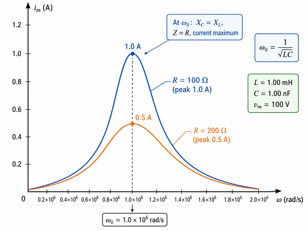
NCERT's plotted case: L = 1.00 mH, C = 1.00 nF gives rad/s; at resonance the peak current for R = 100 is exactly twice that for R = 200 — smaller R, taller and sharper peak.
Key Point (NCERT, emphatic): resonance is exhibited only if both L and C are present — only then can and (out of phase) cancel. There is no resonance in RL or RC circuits.
Tuning, and Other Uses of a Peak
Radio/TV tuning is resonance at work. The antenna feeds the tuning circuit signals from many stations — many driving frequencies at once. Turning the tuner varies a capacitor, changing the circuit's until it matches your station's frequency; that signal alone drives a large current. Selection by resonance.
The airport metal detector (NCERT Example 7.10) is the same physics: the detector coil is part of a circuit tuned near resonance. Metal you carry changes the effective inductance, shifts the circuit off resonance, changes the current — and the change triggers the alarm.
[JEE Tip] At resonance the element voltages are (full source), and — which can be many times the source voltage (voltage magnification). Computing at resonance and being unafraid when it dwarfs the source is a JEE hallmark.
[NEET Important] Three resonance facts asked endlessly: , , . And the frequency: — sharpen your arithmetic.
Solved Examples
Example 1: NCERT's plotted circuit [JEE Numerical]
Find the resonant angular frequency and frequency for L = 1.00 mH and C = 1.00 nF.
Solution:
- , so s.
- rad/s.
- kHz — NCERT's Fig. 7.14 case exactly.
Example 2: Resonance of the 283 V circuit (NCERT Example 7.9 setup) [JEE Numerical]
For L = 25.48 mH and C = 796 F, find the resonant frequency; with = 283 V and R = 3 , find the peak current at resonance.
Solution:
- ; s.
- rad/s ( Hz).
- At resonance : A — compare 56.6 A off resonance (Section 6).
Example 3: Tuning a radio [JEE Numerical]
A tuning circuit has L = 200 H. What capacitance tunes it to an 800 kHz station?
Solution:
- Condition: , so .
- rad/s; .
- F nF.
- Turning the tuning knob is sweeping exactly this C.
Example 4: Voltage magnification at resonance [JEE Numerical]
At resonance, a series circuit (R = 10 , ) is driven by a 220 V source. Find the current and the rms voltage across the inductor.
Solution:
- : A.
- V — ten times the source!
- V too, in exact anti-phase: they cancel, leaving 220 V across R. Large internal voltages, perfectly balanced books.
Example 5: Scaling the resonant frequency [NEET Numerical]
The inductance of a resonant circuit is quadrupled (C unchanged). What happens to ?
Solution:
- .
- gives .
- Answer: the resonant frequency halves. (Quadrupling C would do the same.)
Example 6: Power factor and power at resonance [NEET Numerical]
At resonance, a series LCR circuit (R = 5 ) carries an rms current of 10 A. Find the power factor and the power drawn.
Solution:
- At resonance : power factor (maximum).
- W.
- All of it dissipates in R — L and C are merely exchanging energy with each other.
Example 7: Why no resonance in RL or RC?
Explain NCERT's insistence that resonance needs both L and C.
Solution:
- Resonance is the cancellation of by — possible only because they are 180 degrees apart in phase.
- With one reactance absent, nothing can cancel the other: Z = never falls to R at any finite frequency.
- No minimum in Z, no current peak — no resonance in RL or RC circuits.
Example 8: How a radio selects one station
The antenna delivers signals at many frequencies. Why does only one station play?
Solution:
- Each signal drives the tuning circuit at its own frequency; the circuit responds strongly only near its resonant frequency.
- Tuning varies C until matches the desired station.
- That station's current dwarfs the rest — amplitude selection by resonance.
Example 9: The airport metal detector (NCERT Example 7.10)
Why does walking through a metal detector with coins set it off?
Solution:
- The detector's gateway coil is part of a circuit tuned near resonance with large current.
- Metal passing through changes the coil's effective inductance, shifting — the circuit moves off resonance and the current changes significantly.
- Electronics sense the current change and sound the alarm. Resonance turned into security.
Example 10: Reading the resonance curve
NCERT's -vs- plot shows two curves for R = 100 and 200 (same L, C, = 100 V). Compare their peaks and positions.
Solution:
- Position: both peak at the same — R does not move the resonance.
- Height: peak current : 1.0 A for 100 , 0.5 A for 200 — half.
- Smaller R also makes the peak sharper — the circuit is more selective (the idea behind good tuners).