
Average Power and the Power Factor
Drive a series LCR circuit with ; the current is with and . The instantaneous power is
The second term averages to zero over a cycle, leaving
The factor is the power factor: average power depends not just on voltage and current but on the cosine of the phase angle between them.
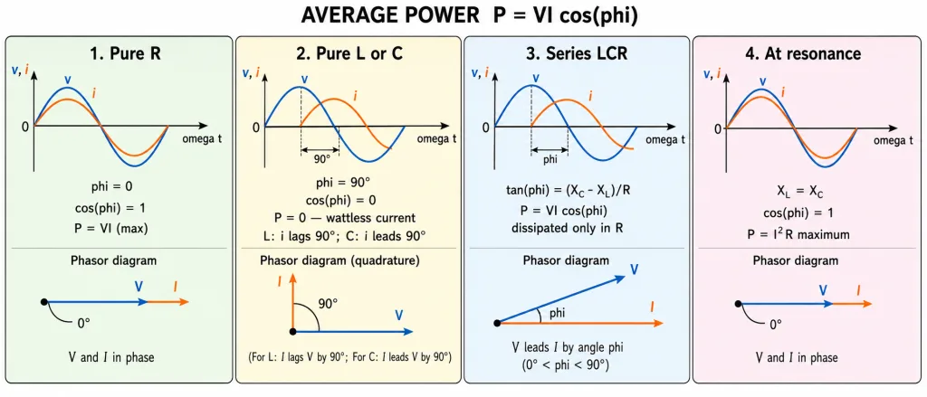
The Four NCERT Cases
- Resistive circuit (pure R): , — maximum power dissipation: .
- Purely inductive or capacitive: degrees, — no power dissipated even though current flows. This current is called the wattless current.
- LCR series circuit: with . Crucially, power is dissipated only in the resistor — never in ideal L or C.
- At resonance: , so , : maximum power .
Key Point: since , the power formula can always be rewritten — whatever the circuit, the resistor takes all the heat.
[NEET Important] 'Wattless current' = the current in a purely reactive circuit ( degrees): real amperes, zero average watts. The phrase itself is asked as a one-mark definition.
Why Engineers Fight Low Power Factor (NCERT Example 7.7)
(a) Why transmit at high voltage? Transmission cables carry power . For a given P, a higher V means a smaller I — and the line loss falls as the square. So power is transported at the highest practical voltages (and stepped down near the consumer — Section 7).
(b) Why is low power factor expensive? For fixed required power P and supply voltage V, the current is . A small forces a large current, and the line loss balloons. Suppliers therefore want loads with power factor close to 1.
The fix: most industrial loads (motors!) are inductive, with current lagging. Installing a capacitor in parallel supplies a leading component that cancels the lagging (wattless) component, raising towards 1 without changing the useful power.
[JEE Tip] Keep the two power formulas straight: the instantaneous power oscillates at (twice the supply frequency); the average is . Questions about 'frequency of power oscillation' want — 100 Hz on the 50 Hz mains.
Solved Examples
Example 1: The 283 V LCR circuit (NCERT Example 7.8)
A sinusoidal voltage of peak 283 V, 50 Hz, drives a series circuit with R = 3 , L = 25.48 mH, C = 796 F. Find (a) Z, (b) the phase, (c) the power dissipated, (d) the power factor.
Solution:
- (a) ; ; .
- (b) — net inductive, current lags.
- (c) A; A; W.
- (d) . Check: W. Consistent.
Example 2: The same circuit at resonance (NCERT Example 7.9)
If the source frequency is changed to the resonant frequency, find the impedance, current and power.
Solution:
- At resonance and .
- A, so A.
- kW — nearly three times the off-resonance power. Maximum power at resonance.
Example 3: A straight power-factor computation [NEET Numerical]
An AC circuit draws 2 A (rms) from a 220 V source with the current lagging the voltage by 60 degrees. Find the power consumed.
Solution:
- .
- W.
- The rest of the apparent power (VI = 440 V A) is the reactive, sloshing share — only 's share becomes heat.
Example 4: Wattless in numbers [NEET Numerical]
A pure inductor on a 220 V source carries 5 A (rms). How much average power does the source deliver?
Solution:
- Pure inductor: , .
- W.
- Five real amperes, zero average watts — the wattless current in person.
Example 5: Power factor from the impedance triangle [JEE Numerical]
A series circuit has R = 30 and Z = 50 , drawing rms current 2 A. Find the power factor and the power dissipated.
Solution:
- .
- W. (Equivalently W.)
- All 120 W appear in R; the reactance handles only the borrowed energy.
Example 6: Resonance vs off-resonance power [JEE Numerical]
A series LCR circuit (R = 3 ) is driven by a fixed 200 V rms source. Compare the power at resonance with the power when Z = 5 .
Solution:
- At resonance: A; kW.
- Off resonance: A; kW.
- Ratio — power falls off the peak as the square of the impedance ratio.
Example 7: Why high-voltage transmission? (NCERT Example 7.7a)
For circuits transporting electric power, why is a low power factor implied to be wasteful, and why is power transmitted at high voltages?
Solution:
- The cable must deliver . For fixed P, raising V lowers I proportionally.
- Line loss is — quartering the current cuts the loss sixteen-fold.
- Hence: generate, step UP to very high voltage, transmit thin-current power across the country, step DOWN at the destination.
Example 8: The cost of low power factor (NCERT Example 7.7b)
A factory needs power P from the V-volt mains at power factor 0.5. Compare its line current (and line losses) with a unity-power-factor load of the same P.
Solution:
- : at the current is twice the unity-pf current.
- Line losses become four times larger.
- That's why suppliers penalise low power factor — and why factories install capacitor banks to cancel the lagging wattless component.
Example 9: Where exactly is power dissipated?
In a series LCR circuit carrying current, identify where the average power goes, and why L and C take none of it.
Solution:
- Across L and C the voltage is 90 degrees out of phase with the current — their average power is zero; they only borrow and return energy.
- Across R, voltage and current are in phase: average power .
- Hence — the source's net output all lands in the resistor as heat.
Example 10: The frequency of power oscillation
On the 50 Hz mains, at what frequency does the instantaneous power delivered to a resistor oscillate?
Solution:
- .
- The oscillating part has angular frequency — twice the supply's.
- Answer: 100 Hz. (This is why some lamps flicker at 100 Hz, not 50 Hz.)