
Mutual Induction, Engineered
A transformer changes an alternating voltage from one value to another (greater or smaller) using mutual induction (Chapter 6).
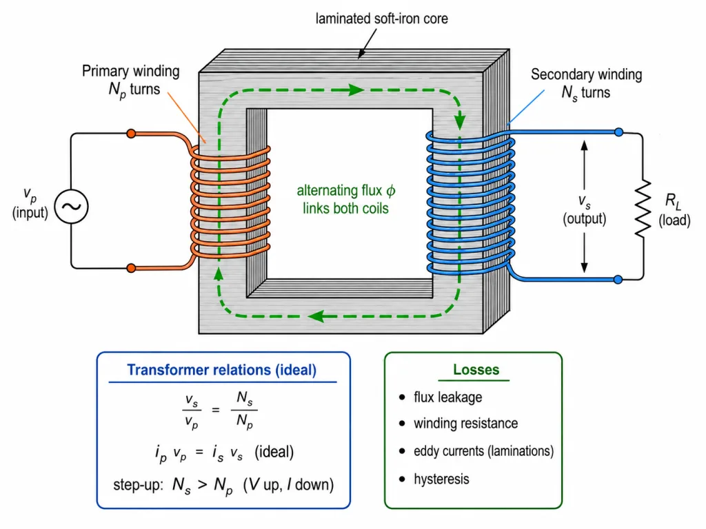
Construction: two coils, insulated from each other, wound on a soft-iron core — either one on top of the other, or on separate limbs of the core. The primary coil ( turns) is the input; the secondary ( turns) is the output.
Working: an alternating voltage across the primary drives an alternating current, producing an alternating flux in the core that links both coils. By Faraday's law the secondary acquires an induced emf
while the same changing flux produces a back emf in the primary (which equals the applied for a negligible-resistance primary).
The Transformer Equations
Dividing the two emf relations (with , for an ideal transformer):
The same flux change per turn in both coils — so voltage divides in proportion to turns. NCERT's three small print assumptions: (i) negligible primary resistance, (ii) the same flux links both coils (very little leakage), (iii) small secondary current.
If the transformer is 100 percent efficient (no losses), power in = power out:
The same ratios hold for amplitudes and rms values.
- Step-up (): voltage up, current down — e.g. turns 220 V at 10 A into 440 V at 5 A (NCERT's own example).
- Step-down (): voltage down, current up.
Key Point: a transformer trades voltage for current at (nearly) constant power. It is not a power amplifier — and it does nothing at all on steady DC (no changing flux, no induction!).
Real Transformers: The Four Losses, and the Grid
Well-designed transformers exceed 95 percent efficiency, but small losses persist (NCERT's four, with remedies):
- Flux leakage — not all primary flux links the secondary (air gaps, poor design). Remedy: wind one coil over the other.
- Winding resistance — wires heat up (). Remedy: thick wires for high-current windings.
- Eddy currents — the alternating flux induces swirling currents in the iron core itself, heating it. Remedy: a laminated core (thin insulated sheets) that breaks up the current loops.
- Hysteresis — repeated magnetisation reversal of the core dissipates energy. Remedy: core material with low hysteresis loss (soft iron).
The large-scale payoff: at the generating station the voltage is stepped up (reducing the current and hence the line loss), transmitted cross-country, then stepped down in stages — at area sub-stations, then utility poles — to the 240 V that reaches homes.
[NEET Important] The four losses + remedies are a standing 3-mark Board question and a NEET favourite. Learn them as pairs (loss → fix).
Solved Examples
Example 1: NCERT's own numbers [NEET Numerical]
A transformer has 100 primary turns and 200 secondary turns. The input is 220 V at 10 A. Find the output voltage and current (ideal transformer).
Solution:
- : V — stepped up.
- Current steps down by the same ratio: A.
- Check: power in W; power out W. Conserved.
Example 2: A step-down at the sub-station [JEE Numerical]
A 4400 V line feeds a step-down transformer delivering 220 V to a locality drawing 2.2 kW. Find the turns ratio, the secondary current and the primary current (ideal).
Solution:
- .
- A.
- A — twenty times smaller, exactly the inverse of the voltage ratio.
Example 3: Counting turns [NEET Numerical]
A transformer must convert 220 V mains to 11 V for a doorbell. Its primary has 400 turns. How many turns does the secondary need?
Solution:
- .
- turns.
- Small voltage, few turns — the flux change per turn is identical in both coils.
Example 4: A 90 percent efficient transformer [JEE Numerical]
A transformer draws 1000 W from the mains but delivers only 90 percent of it to the 220 V secondary circuit. Find the output power and the secondary current.
Solution:
- W.
- A.
- The missing 100 W heats the transformer — flux leakage, winding resistance, eddy currents, hysteresis.
Example 5: The transmission-loss miracle [JEE Numerical]
A plant must send 22 kW through a line of total resistance 10 . Compare the line losses when transmitting (a) at 220 V, (b) stepped up to 22 kV.
Solution:
- (a) A: loss kW — more than the power being sent! Absurd.
- (b) A: loss W — utterly negligible.
- Stepping the voltage up 100x cut the loss by . This single calculation is why the grid exists.
Example 6: Flux change per turn [NEET Numerical]
The primary (300 turns) of a transformer is fed such that the flux in the core changes at Wb/s. Find the emf per turn and the secondary emf if .
Solution:
- Emf per turn V — the same for every turn of both coils.
- Primary back emf: V; secondary: V.
- Ratio : the turns ratio, of course.
Example 7: Why no transformer on DC?
A student connects a transformer's primary to a battery, expecting a stepped-up DC output. What actually happens and why?
Solution:
- A steady current makes a steady flux — and induction needs .
- Apart from a momentary kick at switch-on/off, the secondary shows zero voltage.
- (Worse: with no back emf to limit it, the primary current grows dangerously — transformers on DC tend to burn.) Transformers are an AC-only technology, which is precisely why the grid is AC.
Example 8: The four losses, with remedies
List the energy losses in a real transformer and one remedy for each.
Solution:
- Flux leakage → wind the coils one over the other.
- Winding resistance ( heat) → use thick copper wire.
- Eddy currents in the core → laminate the core (thin insulated sheets).
- Hysteresis (repeated magnetisation reversal) → use a core material with low hysteresis loss, like soft iron. Even so, good transformers already exceed 95 percent efficiency.
Example 9: Ideal-transformer assumptions
State the three assumptions behind .
Solution:
- The primary resistance (and current) is small — applied voltage equals back emf.
- The same flux links both coils — negligible leakage from the core.
- The secondary current is small (light loading).
- Real, well-designed transformers approximate all three closely — hence efficiencies above 95 percent.
Example 10: From power plant to your wall
Trace the voltage of electrical power from generation to a home, naming the transformer at each stage.
Solution:
- At the plant: generated at several kV, immediately stepped UP to very high voltage for transmission (small current, tiny loss).
- Area sub-station: stepped down to distribution levels.
- Utility pole / local transformer: stepped down again to the 240 V (rms) that enters homes. Up once for the journey, down in stages for safety.