
Why do we even need EMF?
In the last section we studied what happens to energy inside a resistor — it gets dissipated as heat. But we skipped over an obvious question: where does the energy come from in the first place?
Think of a water fountain. Water flows out of the spout, falls down, and collects at the bottom. Left alone it would just sit there. To make the fountain work continuously, you need a pump that lifts water back up — something that gives energy to the water.
A circuit needs the same thing. A resistor dissipates electrical energy; something else has to keep pumping charges "uphill" — from low potential to high potential inside itself — so that they can flow "downhill" through the external circuit again. That something is a source of EMF — usually a cell or battery.
In this section we'll open up the cell and look at what's really going on. We'll define EMF precisely, meet the unavoidable companion called internal resistance, and derive the single most-used relation about cells:
This one line controls every numerical in this chapter that involves a real battery.
Electromotive force (EMF) — the real definition
Despite the name, EMF is not a force. It's an energy-per-charge quantity (same units as potential difference — volts) and represents the work a source does to move a unit positive charge from its negative terminal to its positive terminal inside the cell.
Definition: The EMF of a source is the work done per unit charge by the non-electrostatic force inside the source in carrying the charge from the low-potential terminal to the high-potential terminal:
Unit: volt (V), same as potential difference. .
Inside a chemical cell, this non-electrostatic force is the result of chemical reactions at the electrodes. The chemistry pushes positive ions towards one electrode and electrons towards the other, creating a potential difference that the cell can maintain even when current flows.
Key facts about EMF:
- is a property of the cell.
- EMF is the terminal voltage in the open circuit.
- The energy converted by an ideal cell in driving charge around a circuit is .
- When a cell delivers current for time , the electrical energy supplied by the cell is .
[JEE Tip] Do not confuse EMF with terminal voltage. EMF is what the cell can give; terminal voltage is what it does give when current flows. They are equal only at .
Internal resistance — the catch
A real cell is not just a source of EMF. When current flows, the electrolyte between the electrodes also behaves like a resistor: ions moving through it collide with each other and with electrode surfaces, and some energy is lost inside the cell as heat.
We model this by drawing the cell as an ideal EMF source in series with a resistor , the internal resistance of the cell.
What decides how big is?
- Distance between electrodes: more space for ions to travel means larger .
- Area of the electrodes: bigger plates in contact with electrolyte mean smaller .
- Concentration of the electrolyte: more concentrated electrolyte means more charge carriers and smaller .
- Temperature: higher temperature makes ions move faster, so decreases.
- Age and usage: as chemicals are consumed, grows.
Typical values: fresh dry cell , lead-acid cell to .
[NEET Important] Internal resistance is inside the cell — you cannot physically separate from . But in circuit diagrams we represent them as separate components in series.
The key relation:
Now let us connect a cell (EMF , internal resistance ) to an external resistor and see what the voltmeter reads across the cell's terminals.
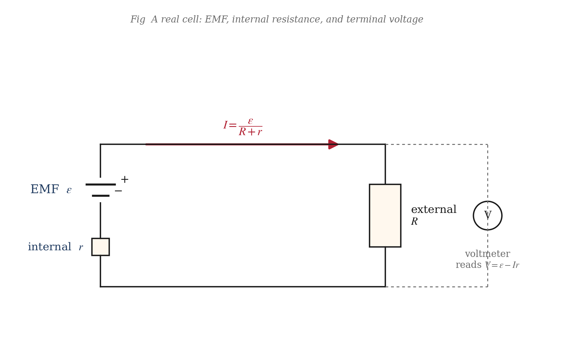
Applying Kirchhoff's loop rule:
So the current is:
The terminal voltage is the potential difference between the cell's terminals as seen from outside. That is the drop across :
So,
Consequences:
- Open circuit ():
- Current drawn ():
- Short circuit (): and
[JEE Tip] A cell with very small behaves close to an ideal voltage source. A cell with large loses terminal voltage quickly under load.
Charging vs discharging — sign of matters
The relation applies during discharge, when the cell acts as a source.
Case 1: Discharging
Case 2: Charging
When an external source drives current into the positive terminal of the cell,
That is why a battery charger must supply a voltage higher than the battery's EMF.
The versus graph
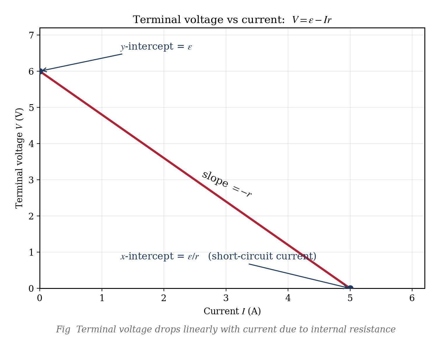
Plotting terminal voltage against current gives a straight line:
- y-intercept:
- slope:
- x-intercept:
[JEE/NEET Trap] If the cell is being charged, use , not .
Power, heating, and efficiency
Total electrical power supplied by the cell per second:
This splits into:
- Useful power delivered to the load :
- Power wasted as heat inside the cell:
Check:
Efficiency of a cell:
So when , and when .
Maximum power transfer theorem:
This is maximum when:
At that condition,
The efficiency there is 50%.
[JEE Tip] Maximum power transfer and maximum efficiency are not the same.
How do we measure and ?
Method 1: Two-load method
Connect the cell to two different loads and . Measure currents and (or terminal voltages and ). Then:
If voltages are measured,
so
Method 2: Potentiometer
A potentiometer draws zero current from the cell at balance, so it reads the true EMF.
Method 3: Voltmeter + load
- Open circuit:
- With load :
- Then and
[NEET Important] An ideal voltmeter has infinite resistance and reads the true EMF.
Common traps and quick summary
Trap 1: Mixing up EMF and terminal voltage
- is a property of the cell.
- is the actual terminal voltage under load.
- They are equal only at .
Trap 2: Sign of during charging
- Discharging:
- Charging:
Trap 3: Short circuit
- When ,
- Very large currents can be dangerous.
Trap 4: Why old batteries fail
- EMF drops only a little.
- Internal resistance rises sharply.
- Terminal voltage then collapses under load.
Quick-recall formulas
| Quantity | Symbol | Formula |
|---|---|---|
| EMF | ||
| Current | ||
| Terminal voltage (discharge) | ||
| Terminal voltage (charge) | ||
| Short-circuit current | ||
| Power to load | ||
| Power lost internally | ||
| Efficiency | ||
| Max-power condition | ||
| Max load power |
Example 1: Open-circuit vs closed-circuit reading
A cell reads 1.50 V when connected to a voltmeter of very high resistance. When a 2.0 Ω resistor is connected across it, an ammeter in the circuit reads 0.60 A. Find: (a) the EMF, (b) the terminal voltage under load, (c) the internal resistance.
Solution: The high-resistance voltmeter draws essentially zero current, so its reading is the EMF:
Terminal voltage under load:
Internal resistance:
Answer: (a) V (b) V (c)
Example 2: Two-load method — find and
When a battery is connected across a 3 Ω resistor, the current is 1.5 A. When the same battery is connected across a 1 Ω resistor, the current rises to 3.0 A. Find the EMF and internal resistance of the battery.
Solution: For the first case:
For the second case:
Equating,
Then,
Answer: V,
Example 3: Short-circuit current and the danger of small
A lead-acid car battery has V and internal resistance . What is the short-circuit current?
Solution: For short circuit, , so
Answer: A
Example 4: Charging a battery ( case)
A 12.0 V car battery has internal resistance 0.04 Ω. A charger forces a current of 20 A into the positive terminal of the battery. What is the terminal voltage of the battery during charging?
Solution: During charging,
Answer: V
Example 5: Maximum power transfer
A cell of EMF 6 V and internal resistance 2 Ω is connected to a variable resistor . For what value of is the power delivered to maximum? What is this maximum power?
Solution: Maximum power transfer occurs when:
Then,
Answer: , W
Example 6: Efficiency of a cell
A cell has EMF 2.0 V and internal resistance 0.5 Ω. It is connected to an external resistance of 1.5 Ω. What is the efficiency of the cell?
Solution:
Answer:
Example 7: Why an old battery dies suddenly
A dry cell has EMF 1.5 V. When new, its internal resistance is 0.5 Ω. After a year of heavy use, its internal resistance grows to 10 Ω while EMF drops only to 1.4 V. Compare the current and terminal voltage delivered to a 3 Ω torch bulb.
Solution: New cell:
Old cell:
Answer:
- New cell: A, V
- Old cell: A, V
Example 8: Voltmeter with finite resistance
A voltmeter of resistance 100 Ω is used to measure the EMF of a cell of true EMF 2.00 V and internal resistance 5 Ω. What does the voltmeter actually read?
Solution: Current drawn by voltmeter:
Voltmeter reading:
Answer: V
Example 9: How much power does the cell waste in itself?
A battery has V and . It delivers current to a 3 Ω load. Find: (a) current, (b) power delivered to the load, (c) power wasted internally, (d) total power supplied by the EMF source, (e) efficiency.
Solution:
Answer: (a) A (b) W (c) W (d) W (e)
Example 10: Finding internal resistance from two voltmeter readings
The terminal voltage of a cell is 3.2 V when it delivers a current of 0.4 A, and 3.0 V when it delivers 0.8 A. Find the EMF and internal resistance.
Solution: Using we get
Subtracting,
Then,
Answer: V,
Example 11: Two batteries connected in opposition
A 6 V battery of internal resistance 0.5 Ω and a 4 V battery of internal resistance 1.0 Ω are connected in opposition through a 2 Ω resistor. What current flows, and what is the terminal voltage of each battery?
Solution: Net EMF:
Total resistance:
Current:
For the 6 V cell (discharging):
For the 4 V cell (charging):
Answer: A, V, V
Example 12: Designing for a specific efficiency
A cell has EMF 1.5 V and internal resistance 0.3 Ω. What external resistance should be connected so that the efficiency is exactly 90%? What is the current and power delivered to the external resistor?
Solution: From we get
Current:
Power delivered to the load:
Answer: , A, W