
Why do we need Kirchhoff's rules?
Ohm's law and the series/parallel formulas can handle many circuits. But the moment you have two or more batteries, or a resistor that sits on a "bridge" between branches, the simple rules break down.
Try this: take two batteries with different EMFs, wire them with three resistors in a shape that has two separate loops, and ask for the current in the middle resistor. There's no way to collapse that into a single equivalent resistance — the current has to be found by applying conservation laws directly.
That's exactly what Kirchhoff's two rules do. They are nothing mysterious — they are just:
- Conservation of charge applied to a junction (the junction / current rule, KCL)
- Conservation of energy applied around a closed loop (the loop / voltage rule, KVL)
Once you write these as equations, the whole circuit becomes a set of linear equations you can solve for the unknown currents. This section teaches that conversion: from a messy diagram to a clean system of equations.
Kirchhoff's junction rule (KCL)
Statement. At any junction (node) of a circuit, the algebraic sum of currents is zero:
Or equivalently: the sum of currents flowing into a junction equals the sum of currents flowing out.
Why it's true. Charge is conserved. A junction is just a point in the wire; it can't store charge. Whatever flows in must flow out at the same rate, otherwise charge would pile up indefinitely — and steady-state circuits have no such pile-ups.
How to apply it. Label each branch current with an arrow and a name (say , , ). At each junction, write:
It doesn't matter if you guessed the direction of an arrow wrong — if your answer comes out negative, it just means the current actually flows the other way.
Example: At a T-junction where flows in and , flow out:
[JEE Tip] For a network with junctions, only of the junction equations are independent. If you write all , the last one will be a combination of the others and gives no new information.
Kirchhoff's loop rule (KVL)
Statement. Around any closed loop of a circuit, the algebraic sum of the potential differences (rises and drops) is zero:
Why it's true. Potential is a single-valued function of position in an electrostatic circuit — if you walk around a loop and come back to your starting point, you must be back at the same potential. The algebraic sum of all rises and drops on the way has to be zero. Equivalently, energy is conserved: the energy gained from sources around a loop equals the energy lost in resistors.
Sign conventions (the single biggest source of errors — memorise this):
- Traversing a resistor in the direction of current: potential drops → write .
- Traversing a resistor opposite to the current: potential rises → write .
- Moving through a cell from − to + terminal: potential rises by → write .
- Moving through a cell from + to − terminal: potential drops by → write .
(Internal resistance is handled exactly like any other resistor — it belongs with the cell, but the drop follows the same "same-direction-as-current ⇒ drop" rule.)
[NEET Important] The sign rule is about the direction you walk through the element, not about which side of it you're on. Always mark arrows and pick a walk direction before writing the loop equation.
Visualising both rules together
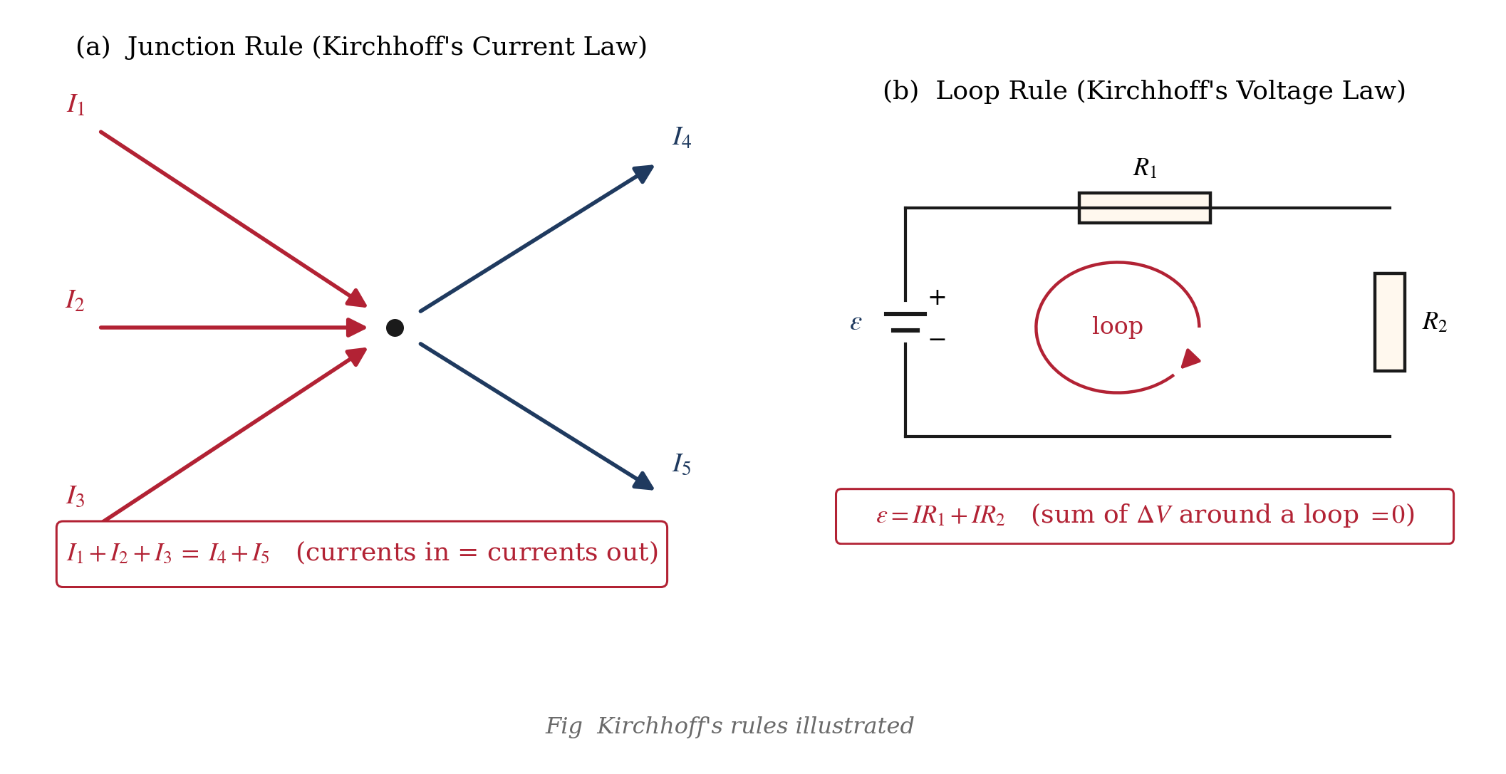
The image above captures the two rules side by side:
- Left (junction rule): three branches meet at a node. Currents are labelled with arrows; the equation at the junction reads (or with the sign convention that currents into the node are positive).
- Right (loop rule): a closed loop with a cell and two resistors. Walking around the loop in the arrow direction and adding up for cells and for resistors gives zero.
A clean way to remember both rules: charge doesn't accumulate (junction rule), energy doesn't get created for free (loop rule).
A systematic recipe for solving any circuit
For a network with several EMF sources and resistors, here is a step-by-step procedure that always works.
Step 1: Draw and label. Redraw the circuit neatly. Mark every branch with a current arrow and a name (). You can guess the direction — it's fine.
Step 2: Apply junction rule. At each junction, write . Use the junction equations to eliminate as many currents as you can. If the circuit has junctions, of these are independent.
Step 3: Identify independent loops. For a circuit with branches and junctions, the number of independent loops is . In a two-loop circuit you'll need exactly two loop equations.
Step 4: Apply loop rule to each loop. Pick a traversal direction (clockwise or counter-clockwise — whichever is convenient). Walk around and write , honouring the sign convention:
- Cell from − to +:
- Cell from + to −:
- Resistor with current:
- Resistor against current:
Step 5: Solve the linear system. You'll have as many equations as unknowns. Solve by substitution, elimination, or (for 3+ unknowns) determinants / matrix methods.
Step 6: Interpret negative answers. A negative current simply means the actual flow is opposite to your assumed arrow. The magnitude is correct; just reverse the direction.
Alternative: Loop currents (mesh analysis). Instead of branch currents, assign a single circulating current to each loop. The current in a shared branch is the algebraic sum of the two loop currents. For two-loop problems this reduces the algebra considerably.
[JEE Tip] Always traverse each loop in the same direction (say, all clockwise). It's easier to catch sign errors that way.
Walking through a sample two-loop circuit
Let's apply the recipe to the classic two-loop network in the figure below.
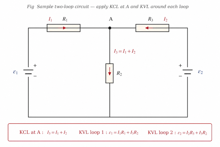
Take EMFs V (left loop source) and V (right loop source). Resistors: Ω, Ω (shared middle branch), Ω. Internal resistances are absorbed into and .
Let be the current in the left branch (through and ), be the current in the right branch (through and ), both taken to flow into the top node. The middle-branch current flowing down is then, by the junction rule,
Loop 1 (left, clockwise).
Loop 2 (right, clockwise).
Solving gives
The negative sign means the 4 V cell is being charged.
[NEET Important] A negative current answer is physically meaningful: it means the actual current direction is opposite to the one assumed.
Mesh (loop-current) analysis — the shortcut
For two-loop problems, this approach is often faster than branch-current analysis.
Assign a mesh current to each independent loop, usually all clockwise. Let and be the mesh currents in the left and right loops. A resistor shared by two meshes has current equal to the algebraic difference of the two mesh currents.
For the shared resistor , the current is downward if .
The loop equations can be written as:
Diagonal entries are sums of resistances in each mesh. Off-diagonal entries are negatives of shared resistances.
This method extends directly to three or more loops.
Quick reference and summary
| Element in loop | Traverse direction | Write |
|---|---|---|
| Cell, − to + | any | |
| Cell, + to − | any | |
| Resistor | with current | |
| Resistor | against current |
Junction rule:
Loop rule:
For junctions and branches, the number of independent loop equations is , and the number of independent junction equations is .
These two rules are the most general tools for DC circuit analysis.
Example 1 — Apply junction rule at a T-node
Three wires meet at a point. Currents of 3 A and 5 A flow into the junction through two of them. What is the current in the third wire, and which way does it flow?
Solution: Using KCL,
So the third current flows out of the junction.
Answer: 8 A, flowing out of the junction.
Example 2 — Single loop with two cells aiding
Two cells of EMFs 6 V and 4 V with internal resistances 1 Ω and 2 Ω respectively are connected in series, aiding each other, across an external resistor of 3 Ω. Find the current in the circuit.
Solution: Net EMF:
Total resistance:
Current:
Answer: 1.67 A.
Example 3 — Single loop with cells opposing
Two cells of EMFs 6 V and 4 V with internal resistances 0.5 Ω and 0.5 Ω are connected opposing each other across an external 3 Ω resistor. Find the current and its direction.
Solution: Net EMF:
Total resistance:
Current:
The current is driven by the stronger 6 V cell, so the weaker 4 V cell is being charged.
Answer: 0.5 A; the 4 V cell is being charged.
Example 4 — Two-loop network (branch-current method)
A 12 V cell drives two parallel branches. Branch 1 contains a 4 Ω resistor. Branch 2 contains a 6 Ω resistor in series with a 3 V cell that opposes the 12 V cell. Find the current in each branch and the total current.
Solution: For branch 1:
For branch 2:
Total current:
Answer: A, A, total current = 4.5 A.
Example 5 — Current in a bridge-like shared branch
For the sample two-loop circuit with V, V, Ω, Ω, Ω, find all three branch currents.
Solution: The loop equations are:
Solving,
Then,
Answer: A, A, A.
Example 6 — Cells and resistor in parallel branches
Two cells of EMFs 2 V and 4 V, each of internal resistance 1 Ω, are connected in parallel across an external resistance of 2 Ω. Find the current through the external resistor.
Solution: Let branch currents be and , and load current be .
For the 2 V branch:
For the 4 V branch:
Solving,
So,
Answer: Current through the external 2 Ω resistor is 1.2 A. The 2 V cell is being charged.
Example 7 — Three-loop network (mesh method)
A three-loop triangular network has all resistors equal to 6 Ω. A 12 V source drives loop 1, a 6 V source drives loop 2, and loop 3 has no source. Find the mesh currents.
Solution: The mesh matrix is:
Solving gives:
Answer: A, A, A.
Example 8 — Balanced bridge spotting
In a Wheatstone-style network, four resistors 2 Ω, 4 Ω, 3 Ω, 6 Ω form a diamond with a galvanometer across the middle. Check if the bridge is balanced, and find the galvanometer current.
Solution: Bridge balance condition:
Here,
So the bridge is balanced and no current flows through the galvanometer.
Answer: Balanced bridge; galvanometer current = 0 A.
Example 9 — Current through a galvanometer in an unbalanced bridge
In a Wheatstone network, Ω, Ω, Ω, Ω, galvanometer resistance Ω, and battery EMF = 6 V. Find the current through the galvanometer.
Solution: Let be the upper branch current, the lower branch current, and the galvanometer current in the assumed direction.
The equations are:
Solving gives:
So the galvanometer current has magnitude 0.15 A and flows opposite to the assumed direction.
Answer: A for the chosen sign convention; magnitude = 0.15 A.
Example 10 — Find unknown EMF from known currents
A two-branch circuit has a common 3 Ω output resistor carrying the sum of the branch currents. One branch contains a 10 V ideal cell and a 4 Ω resistor, carrying 1 A toward the junction. The second branch contains an unknown ideal cell and a 6 Ω resistor, carrying 0.5 A toward the junction. Find .
Solution: The output current is:
So the junction potential relative to the common negative terminal is:
For the second branch,
Answer: V.
Example 11 — Potential difference between two points
In a circuit with two cells ( V, Ω) and ( V, Ω) in series aiding with an external resistance 4 Ω, find the potential difference between the free terminals.
Solution: Current:
Potential difference across the external resistor:
Answer: 10.67 V.
Example 12 — Applying KCL/KVL with dependent sources (conceptual)
In a modified circuit, a branch carries a dependent current equal to twice the current in another branch. If the other branch carries A and the dependent branch feeds a 10 Ω resistor, find the voltage across the resistor.
Solution: Dependent current:
Voltage across 10 Ω:
Answer: 10 V.