
Rectification: One-Way Conduction Put to Work
The diode conducts only when forward biased. Apply an alternating voltage across it and current flows only during the half-cycles that forward-bias it — the ac is rectified into one-directional (if still pulsating) output. The circuit doing this is a rectifier.
The Half-Wave Rectifier
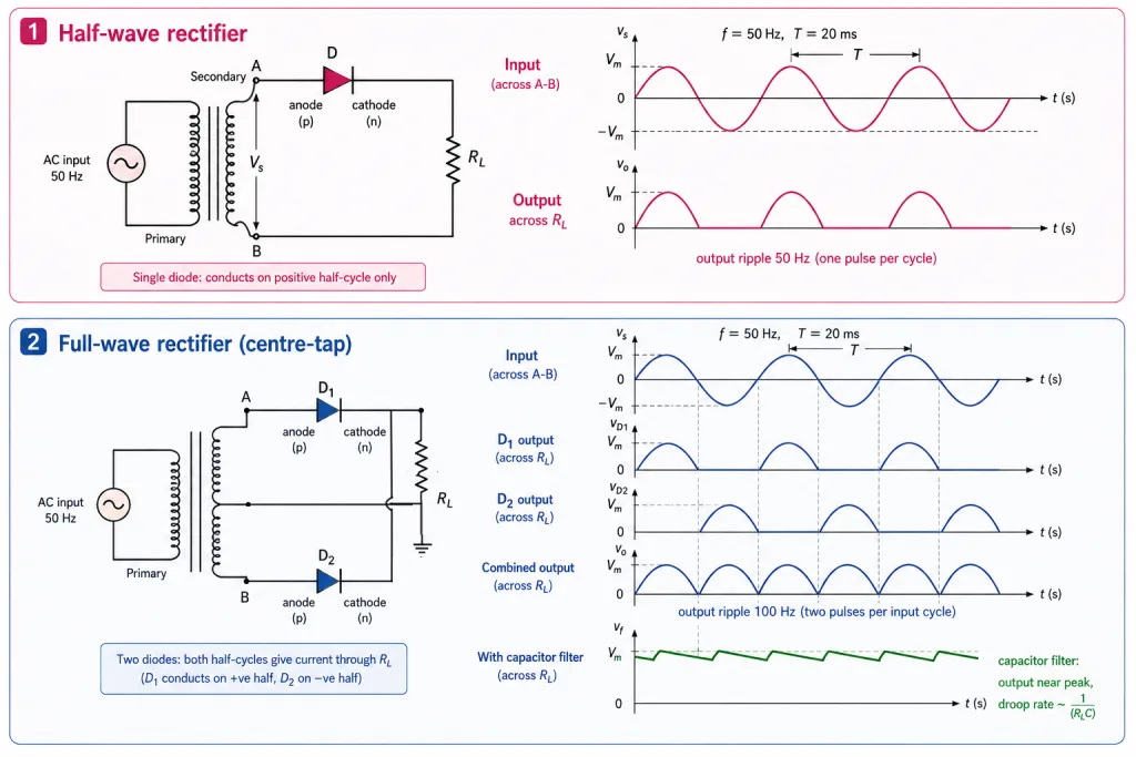
A transformer secondary supplies ac across terminals A and B; a single diode sits in series with the load (NCERT Fig. 14.18):
- A positive: diode forward biased → conducts → output voltage across .
- A negative: diode reverse biased → no conduction (reverse saturation ≈ 0) → no output.
Output appears only for half of each input cycle — hence half-wave. Output frequency = input frequency (50 Hz in → 50 Hz pulses out: one pulse per cycle).
Key Point: The diode's reverse breakdown voltage must exceed the peak ac voltage of the secondary, or the negative half-cycles will destroy it.
The Full-Wave Rectifier (Centre-Tap)
Two diodes, their p-sides connected to the two ends of the secondary, n-sides joined; output taken between that common point and the secondary's centre tap (NCERT Fig. 14.19). Each diode sees only half the total secondary voltage.
- A positive (B negative): conducts, blocks → output across .
- A negative (B positive): conducts, blocks → output again.
Both half-cycles deliver output — full-wave, and clearly more efficient. Output frequency = 2 × input frequency (50 Hz in → 100 Hz pulses: two per cycle). The centre-tap transformer is essential to this circuit; an alternative bridge rectifier uses four diodes and no centre tap.
Rectifier frequency summary (NCERT Exercise 14.6)
| Circuit | 50 Hz input → output ripple |
|---|---|
| Half-wave | 50 Hz |
| Full-wave | 100 Hz |
Filters: From Pulses to DC
The rectified output is unidirectional but pulsating (half-sinusoid humps). To smooth it, connect a capacitor across the load (or an inductor in series) — a filter, so called because it 'filters out the ac ripple'.
How the capacitor filter works
- Voltage rising → capacitor charges (to the peak, if unloaded).
- With a load, it discharges through as the rectified voltage falls, holding the output up.
- Next hump recharges it to the peak.
- Discharge rate is set by the time constant : rate of fall — so a large C gives a slow droop and near-peak output.
Hence capacitor-input filters use large capacitors; the output approaches the peak rectified voltage, and this arrangement is the standard in power supplies.
[NEET Important] The 50/100 Hz pairing is NCERT Exercise 14.6 verbatim and among the most-asked facts of the chapter. [JEE Tip] Circuit-spotting: one diode + load = half-wave; two diodes + centre tap = full-wave; four diodes = bridge (no centre tap needed). Diode count and transformer type identify the circuit instantly.
Solved Examples
Example 1: Output frequencies (NCERT Exercise 14.6)
A 50 Hz ac input feeds (a) a half-wave rectifier and (b) a full-wave rectifier. Find each output frequency.
Solution:
- (a) Half-wave: one output pulse per input cycle → 50 Hz.
- (b) Full-wave: both half-cycles produce pulses → two per cycle → 100 Hz.
- Takeaway: full-wave doubles the ripple frequency, never the amplitude — NCERT's exact exercise, endlessly recycled.
Example 2: Trace the conduction [Board Waveform]
In the centre-tap full-wave rectifier, the voltage at A is negative with respect to the centre tap. Which diode conducts, and why is there still output?
Solution:
- A negative → reverse biased: blocks.
- B, being out of phase, is positive → forward biased: conducts.
- Current flows through in the same direction as before (both diodes feed the common terminal).
- Takeaway: alternate diodes, same load direction — that unidirectional handover is the whole trick.
Example 3: Why the centre tap? [Board Conceptual]
What role does the centre tap play in the two-diode full-wave rectifier?
Solution:
- It provides the common return terminal for the load — output is taken between the joined n-sides and the tap.
- It splits the secondary so the two diode circuits work on opposite half-cycles, each using half the total secondary voltage.
- Without a tap, two diodes cannot make a full-wave rectifier — you'd need the four-diode bridge instead.
- Takeaway: centre-tap = 2 diodes + half voltage each; bridge = 4 diodes + full voltage. Cost trade-offs, same output shape.
Example 4: Peak output of a half-wave rectifier [JEE Numerical]
A half-wave rectifier's secondary supplies 20 V rms at 50 Hz to an ideal diode and load. Find the peak output voltage and output ripple frequency.
Solution:
- Peak: V (ideal diode: no drop).
- Frequency: half-wave → 50 Hz.
- (With a real Si diode: peak ≈ 28.3 - 0.7 = 27.6 V.)
- Takeaway: rms → peak via first; then subtract the cut-in only if the question treats the diode as real.
Example 5: The breakdown-voltage safety rule [Board Conceptual]
Why must a rectifier diode's reverse breakdown voltage comfortably exceed the transformer's peak secondary voltage?
Solution:
- During its blocking half-cycle the diode sits in reverse bias carrying the full peak voltage.
- If that peak reached , breakdown current would flow — uncontrolled, it destroys the diode by overheating.
- NCERT: the breakdown voltage 'must be sufficiently higher than the peak ac voltage at the secondary … to protect the diode'.
- Takeaway: rectifier design begins with a voltage-rating check, not with the forward direction at all.
Example 6: Filter action, step by step [Board Conceptual]
Describe how a capacitor across converts pulsating dc into near-steady dc.
Solution:
- Rising hump: capacitor charges toward the peak.
- Falling hump: capacitor discharges through , holding the output voltage up; the discharge rate .
- Next hump: recharges to the peak; the output ripples gently about a value near the peak voltage.
- Takeaway: large = slow droop = smooth dc — hence the physically large capacitors in power supplies.
Example 7: Choosing C [JEE Numerical]
A full-wave rectifier at 50 Hz feeds = 1 kohm. Roughly how large should C be so the capacitor barely discharges between humps?
Solution:
- Time between humps (full-wave): s = 10 ms.
- Condition: time constant 10 ms → F.
- Practical choice: hundreds of F — hence electrolytic capacitors.
- Takeaway: compare with the ripple period; 'much larger' is the design rule.
Example 8: Which circuit is this? [NEET Spotting]
A rectifier uses four diodes and an ordinary (untapped) transformer. Identify it and its output frequency for 50 Hz input.
Solution:
- Four diodes, no centre tap = the bridge rectifier — NCERT's noted alternative full-wave circuit.
- It rectifies both half-cycles: output ripple at 100 Hz.
- Takeaway: count diodes: 1 → half-wave (50 Hz); 2 + tap → full-wave (100 Hz); 4 → bridge full-wave (100 Hz).
Example 9: Why full-wave is 'more efficient' [Conceptual]
Justify NCERT's claim that the full-wave circuit is more efficient than the half-wave.
Solution:
- The half-wave rectifier wastes every negative half-cycle — no output half the time.
- The full-wave circuit converts both halves into output pulses: double the pulses, double the average dc output for the same input.
- Its 100 Hz ripple is also easier to filter (shorter gaps for the capacitor to bridge).
- Takeaway: more output AND smoother output — efficiency in both senses.
Example 10: Inductor as filter [JEE Extra]
NCERT mentions an inductor in series with as an alternative filter. Why does that work?
Solution:
- An inductor opposes changes in current () — it passes steady dc easily but impedes the ac ripple.
- In series with the load it smooths the current the way the parallel capacitor smooths the voltage.
- Both 'appear to filter out the ac ripple and give a pure dc voltage — so they are called filters.'
- Takeaway: capacitor parallel (voltage smoothing), inductor series (current smoothing) — complementary filter philosophies.