
The Semiconductor Diode
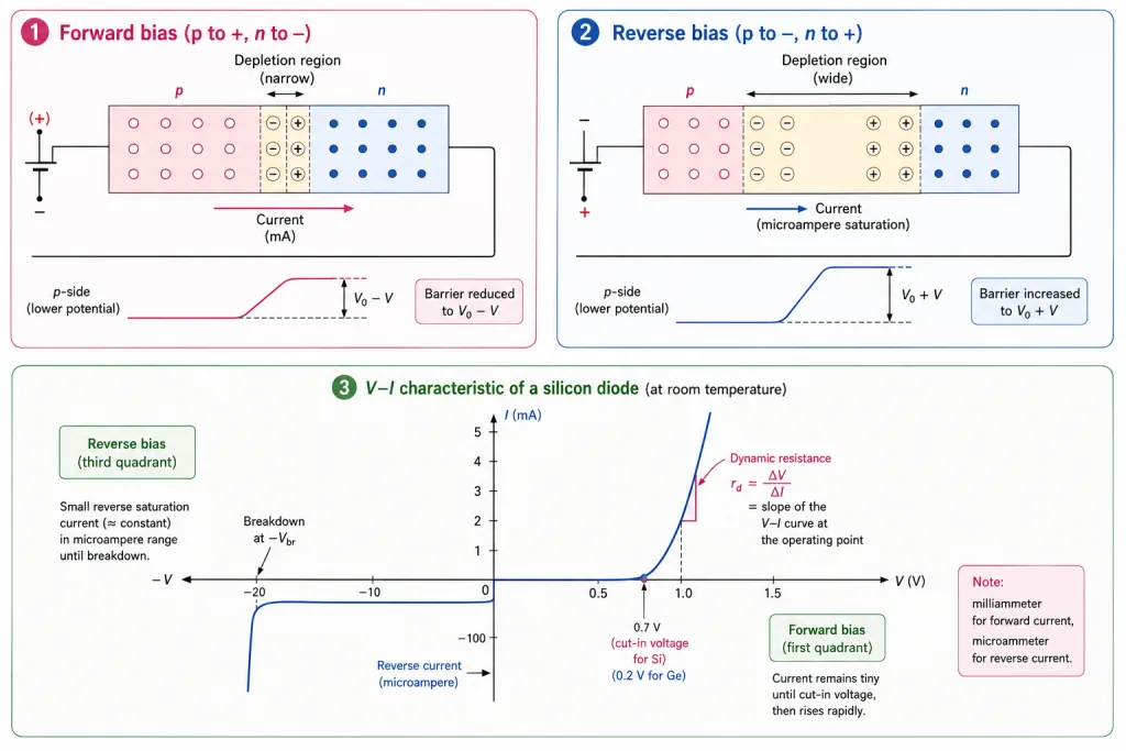
A semiconductor diode is a p-n junction with metallic contacts at its ends for applying external voltage — a two-terminal device. In its symbol, the arrow points in the direction of conventional current under forward bias (from p to n).
The external voltage V alters the equilibrium barrier. Two cases:
Forward Bias: Opening the Gate
Connect p to positive, n to negative. The applied voltage drops mostly across the depletion region (its resistance dwarfs the bulk regions'). V opposes the built-in :
- Effective barrier: — lowered.
- Depletion width: decreases.
Small V → only the most energetic carriers cross → small current. Larger V → barrier falls further → current grows rapidly.
Minority carrier injection
Under forward bias, electrons from n cross to p (becoming minority there) and holes from p cross to n — minority carrier injection. At the junction edges the injected minority concentrations soar, and the resulting gradients diffuse carriers toward the far contacts, sustaining the current. Total forward current = hole diffusion current + electron diffusion current — typically milliamperes (mA).
Reverse Bias: Closing the Gate
Connect n to positive, p to negative. Now V adds to the barrier:
- Effective barrier: — raised.
- Depletion width: increases.
Majority-carrier diffusion is crushed. What remains: minority carriers (electrons on p, holes on n) that wander near the junction get swept across by the field — the drift current, a few microamperes (A).
Why reverse current is voltage-independent
Even a small reverse voltage sweeps every available minority carrier across; the current is limited by the minority-carrier concentration, not the voltage — hence the flat reverse saturation current. (Drift also exists under forward bias but is negligible beside the mA injection current.)
Breakdown
At a critical breakdown voltage , the reverse current rises sharply — a tiny voltage increase causes a huge current change. Unless an external circuit limits the current below the rated value, the junction is destroyed by overheating (equally true for excessive forward current). General-purpose diodes are never operated beyond the reverse saturation region.
The V-I Characteristic
Measured with a variable supply (potentiometer), a milliammeter for forward bias and a microammeter for reverse (NCERT Fig. 14.16):
- Forward: current negligible until the threshold / cut-in voltage — ~0.2 V (Ge), ~0.7 V (Si) — then rises exponentially.
- Reverse: flat A saturation until .
The diode conducts one way only: low forward resistance, enormous reverse resistance — the property behind rectification.
Dynamic resistance
[JEE Tip] NCERT Example 14.4: from the Si characteristic, between 10 and 20 mA, = 0.1 V → ohm; at V = -10 V, I = -1 A → ohm. Forward tens of ohms, reverse tens of megohms — a asymmetry.
Solved Examples
Example 1: Diode resistances from the graph (NCERT Example 14.4)
From the Si diode characteristic: at I = 20 mA, V = 0.8 V; at I = 10 mA, V = 0.7 V; at V = -10 V, I = -1 A. Find the forward resistance at = 15 mA and the reverse resistance at = -10 V.
Solution:
- Forward (dynamic): ohm.
- Reverse: ohm.
- Takeaway: ohms forward, tens of megohms reverse — six orders of one-way-ness, read straight off the curve.
Example 2: Which way is forward? [Board Rapid]
A battery's positive terminal connects to the n-side of a diode. Identify the bias and the expected current scale.
Solution:
- Positive to n = reverse bias (forward needs positive to p).
- Barrier rises to ; only minority-carrier drift flows.
- Current: microamperes (reverse saturation), essentially independent of V until breakdown.
- Takeaway: read the wiring first; the current scale (mA vs A) follows automatically.
Example 3: Barrier arithmetic [NEET Numerical]
A Si junction has = 0.7 V. Find the effective barrier under (a) 0.5 V forward bias, (b) 5 V reverse bias.
Solution:
- (a) Forward: barrier = = 0.7 - 0.5 = 0.2 V (depletion narrows).
- (b) Reverse: barrier = = 0.7 + 5 = 5.7 V (depletion widens).
- Takeaway: forward subtracts, reverse adds — two signs carrying the entire bias story.
Example 4: Why applied voltage falls on the depletion region [Conceptual]
Justify NCERT's statement that the external voltage drops almost entirely across the depletion region.
Solution:
- The depletion region has no free charges — its resistance is very high.
- The p- and n-bulk regions teem with carriers — low resistance.
- In a series chain, voltage divides in proportion to resistance: nearly all of V appears across the high-resistance depletion layer.
- Takeaway: that's why bias acts directly on the barrier — the external volts go exactly where the physics happens.
Example 5: Minority carrier injection [Board Conceptual]
Describe what 'minority carrier injection' means under forward bias.
Solution:
- Forward bias lets electrons from n cross into p — where they are minority carriers; likewise holes from p into n.
- At the junction boundary the minority concentration on each side rises far above its remote value.
- The resulting concentration gradients drive diffusion toward the contacts — this diffusive march IS the forward current.
- Takeaway: forward current is injected-minority diffusion on both sides; total = electron + hole diffusion currents (mA scale).
Example 6: Reading the meters [Board Practical]
Why does the V-I measuring circuit use a milliammeter in forward bias but a microammeter in reverse?
Solution:
- Forward current: injection-driven, typically mA.
- Reverse current: minority-drift saturation, typically A — a milliammeter would read zero.
- Matching meter to scale is essential to see the curve at all.
- Takeaway: the meter choice itself encodes the diode's -plus current asymmetry — asked directly in practicals-based questions.
Example 7: Cut-in voltages [NEET Rapid]
State the threshold (cut-in) voltages of Ge and Si diodes and what happens beyond them.
Solution:
- Ge: ~0.2 V; Si: ~0.7 V.
- Below cut-in: current rises 'very slowly, almost negligibly'.
- Beyond cut-in: current increases significantly (exponentially) for tiny voltage increments.
- Takeaway: the knee of the forward curve — the pair (0.2, 0.7) is among the most-quoted numbers in the chapter.
Example 8: Why reverse current saturates [JEE Conceptual]
Explain why the reverse current is nearly independent of the applied reverse voltage.
Solution:
- Reverse current is fed by minority carriers near the junction.
- Even a small reverse voltage is 'sufficient to sweep the minority carriers' across — the field is never the bottleneck.
- The supply of minority carriers (set by thermal generation, i.e. temperature) limits the current — not the voltage.
- Takeaway: saturation current depends on temperature, not V — so it doubles roughly every 10 °C, a favourite twist.
Example 9: Breakdown and ratings [Board Conceptual]
What happens at , and how can the diode survive it?
Solution:
- At the breakdown voltage the reverse current increases sharply — a slight voltage rise causes a large current change.
- If the external circuit limits the current below the rated value, the junction survives (Zener diodes exploit exactly this regime).
- Unlimited current → overheating → destruction; the same fate awaits excessive FORWARD current.
- Takeaway: ratings are thermal limits; breakdown is not inherently fatal — un-limited breakdown is.
Example 10: Ideal-diode circuit logic [JEE Circuit]
An ideal diode (0 V drop forward, open reverse) is in series with a 200 ohm resistor and a 2 V battery, positive to p. Find the current; then reverse the battery.
Solution:
- Forward: ideal diode = closed switch: mA.
- Reversed: diode = open switch: I = 0.
- (With a real Si diode: mA forward.)
- Takeaway: the on/off switch model solves most JEE diode circuits; refine with the 0.7 V drop when the question supplies it.