
Circuit Diagrams
An electric circuit contains a cell (or battery), a plug key/switch, one or more electrical components and connecting wires. Rather than drawing realistic pictures, we draw a schematic diagram in which each component is shown by a standard symbol. This makes circuits quick to draw and easy to read.
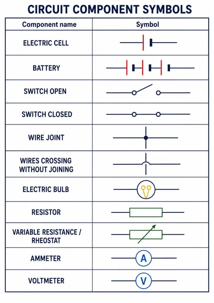
Standard Circuit Symbols
Learn these standard symbols - they appear in every circuit question:
- Electric cell - one long thin line (positive) and one short thick line (negative).
- Battery - two or more cells joined in a row.
- Switch / plug key (open) - a gap in the line; switch (closed) - the gap bridged.
- Wire joint - a dot where wires join; wires crossing without joining - one wire hops over the other with no dot.
- Electric bulb - a circle with a filament (a cross or loop) inside.
- Resistor - a plain rectangle.
- Variable resistance / rheostat - a rectangle with an arrow across it.
- Ammeter - a circle with the letter A (connected in series).
- Voltmeter - a circle with the letter V (connected in parallel).
Key Point: A dot at a crossing means the wires are joined; no dot means they simply cross.
[Exam Tip] In diagrams: the longer line of a cell is the positive terminal; an ammeter (A) goes in series, a voltmeter (V) in parallel.
Solved Examples
Example 1: Reading a cell symbol
In the symbol for a cell, which line represents the positive terminal?
Solution: The longer, thinner line represents the positive (+) terminal, and the shorter, thicker line represents the negative (−) terminal.
Example 2: Joined or crossing?
Two wires cross in a circuit diagram. How do you tell whether they are electrically connected?
Solution: If there is a solid dot at the crossing point, the wires are joined (electrically connected). If there is no dot (one wire drawn hopping over the other), they simply cross without joining.
Example 3: Placing the meters
Where should an ammeter and a voltmeter be placed to measure the current through, and the voltage across, a resistor?
Solution: The ammeter is placed in series with the resistor (so the same current passes through it). The voltmeter is placed in parallel across the resistor (so it reads the potential difference across it).