
From a Single Charge to a Current Element
A current is just a stream of moving charges. Since each charge feels a force in a magnetic field, a wire carrying current must feel a net force too — the sum of forces on all its charge carriers.
Let's derive it cleanly. Consider a short straight piece of wire of length and cross-section carrying a steady current . Let be the number density of charge carriers (electrons in a metal, say), each with charge and drift velocity .
The total number of carriers in this small element is . The force on each carrier is , so the net force on the element is
Now recall from Chapter 3 that the current is . Defining as a tiny length vector pointing along the direction of conventional current flow (same as for positive carriers), we get
This is the force on a current element — the workhorse equation of this section. Notice how the messy details (number of carriers, their drift speed) all collapsed into the macroscopic quantity .
Note: Here refers to the drift velocity of the positive charge carriers so that aligns with the conventional current. In metals where electrons (negative charges) move opposite to the current, still points along the current direction.
Force on a Straight Wire in a Uniform Field
For a straight wire of length carrying current in a uniform magnetic field , we can integrate trivially:
where is a vector of length pointing along the direction of current flow.
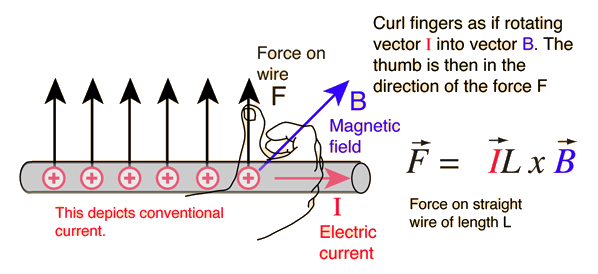
Magnitude
where is the angle between and .
- If the wire is parallel to (): .
- If the wire is perpendicular to (): — maximum.
Direction
Perpendicular to both the wire and , given by the right-hand rule for (or equivalently Fleming's Left-Hand Rule, below).
[JEE Tip] When the wire is not straight (curved or bent), you cannot use directly — you must integrate along the wire. For a uniform field, however, this integration has a beautiful shortcut (next note).
Fleming's Left-Hand Rule
A handy mnemonic for the direction of force on a current-carrying wire: Fleming's Left-Hand Rule.
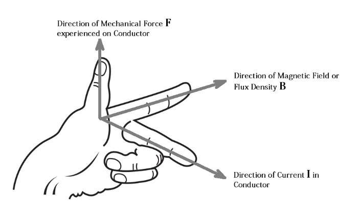
Stretch the forefinger, middle finger, and thumb of your left hand so they are mutually perpendicular:
| Finger | Represents |
|---|---|
| Forefinger | Direction of magnetic field |
| Middle finger | Direction of conventional current |
| Thumb | Direction of force on the wire |
Mnemonic: FBI Rule — Forefinger for B (Field), Index for I (Current), and Thumb for F (Force).
Force on a Closed Loop in a Uniform Field — Why It's Zero
Here's a beautiful result that students often miss: the net force on a closed current loop in a uniform magnetic field is zero.
Proof (one line)
because the closed-loop integral of vanishes — the displacement vector returns to where it started.
What this does not mean
The loop can still experience a net torque even though the net force is zero. That's how electric motors work — a uniform produces a torque on a current loop, spinning it. We'll handle that fully in Section 10.
Where it matters
This zero-force result illustrates how summing all segment forces can give zero net translation; it is distinct from the force between parallel currents, which we will derive formally in Section 9.
[JEE Tip] Two consequences worth remembering:
- In a uniform field, only torque acts on a loop, not net force.
- In a non-uniform field, a current loop does experience a net force — this is how an electromagnet attracts iron, and how magnetic confinement works in plasmas.
Memory Capsule
Lock in these results before moving to motion in a field (Section 4).
The two master equations
| Object | Force |
|---|---|
| Current element | |
| Straight wire of length in uniform |
Magnitude
where is the angle between the wire and the field.
Direction — Fleming's Left-Hand Rule
| Finger | Quantity |
|---|---|
| Forefinger | (Field) |
| Middle | (Current) |
| Thumb | (Force) |
Special cases
- Wire parallel to : .
- Wire perpendicular to : (maximum).
- Wire is curved: integrate along the wire. In a uniform field, the result for a wire from point A to point B depends only on the straight vector , not on the path.
Closed loop in a uniform field
- Net force = 0 (always, for any shape).
- Net torque may be non-zero — that's the motor principle (Section 10).
- In a non-uniform field, a closed loop does experience a net force (electromagnet pulling on iron).
One-line takeaway
The magnetic field pushes wires the same way it pushes charges — but through the macroscopic handle of current, .
Solved Examples
Example 1: Force on a horizontal current-carrying wire
A horizontal wire of length m carries a current A from east to west. It lies in a region where T points vertically downward. Find the magnitude and direction of the magnetic force on the wire.
Solution. Use .
Magnitude:
Direction: Fleming's Left-Hand Rule — forefinger down (along ), middle finger west (along ), thumb points south.
Example 2: Wire balanced against gravity
A horizontal wire of mass g and length cm carries a current in a uniform horizontal magnetic field T (perpendicular to the wire). What current is required to make the magnetic force on the wire exactly support its weight? Take m/s².
Solution. For levitation, magnetic force = weight:
(The direction of current must be chosen so that points upward — left-hand rule decides which way.)
Example 3: Wire at an angle
A straight wire of length m carries A in a uniform magnetic field of T. The wire makes an angle of with . Find the force on the wire. (.)
Solution. Use .
The direction is perpendicular to the plane containing the wire and .
Example 4: Force on a curved wire in a uniform field
A semicircular wire of radius carrying current lies in the plane of the page. A uniform magnetic field points perpendicular to the plane (into the page). The wire's two ends are joined to the rest of a circuit by straight leads. Find the net force on the semicircular portion alone.
Solution. Here's a beautiful shortcut. In a uniform field,
where is the straight chord from the start of the semicircle to its end. For a semicircle of radius , that chord has length .
Direction: perpendicular to the chord , in the plane of the page, given by the right-hand rule on .
Note: this trick works only because the field is uniform. The result is independent of how curved the wire is — only the endpoints matter.
Example 5: Closed loop in a uniform field
A square loop of side m carries a current of A in a uniform field T perpendicular to the loop's plane. Find the net force on the loop.
Solution. The net force on any closed loop in a uniform field is zero:
So regardless of the current, side length, or field magnitude. (The loop may still experience a non-zero torque — that's a different question, treated in Section 10.)
Example 6: Power line in Earth's field
A horizontal transmission line carries A from north to south. The horizontal component of Earth's magnetic field at that location is T, pointing north. Find the force per unit length on the wire.
Solution. Force per unit length: .
Here current direction is south, field direction is north (anti-parallel, ), so
No magnetic force from the horizontal component. Only the vertical component of Earth's field would produce a force on this wire — which is small ( T at many locations, giving N/m horizontally east or west).
Example 7: Current-carrying wire in a field at
A wire of length m carries a current of A. It is placed in a uniform magnetic field of T such that the wire makes an angle of with the field. Calculate the force on the wire.
Solution. Use .
Example 8: Maximum and minimum force
A wire of length m carrying A is placed in a magnetic field of T. Find (a) the maximum possible force on the wire (b) the minimum possible force.
Solution. Use .
(a) Maximum at (wire perpendicular to ):
(b) Minimum at or (wire parallel or anti-parallel to ):
Takeaway: by rotating the orientation of the wire, you can tune the force from to continuously.