
Construction of the Moving Coil Galvanometer
This section is the grand finale of the chapter: a beautiful instrument that turns every theoretical idea we have built — magnetic fields, current loops, dipole moments, torques — into a usable measuring device for tiny electric currents.
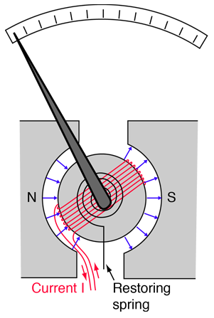
Main parts
- Rectangular coil ( turns): wound on a light non-metallic (aluminium or paper) rectangular frame. This is the moving part — it rotates when current flows.
- Permanent magnet with curved (concave) pole pieces: these produce a strong magnetic field. The concave shape makes the field point radially across the gap.
- Soft iron cylindrical core: placed at the centre of the coil. It (a) intensifies the magnetic field, and (b) together with the curved pole pieces, ensures that the field is always radial — i.e., always in the plane of the coil, perpendicular to its sides.
- Two phosphor-bronze ribbon springs: one at the top and one at the bottom. They both carry current to the coil and provide a restoring torque proportional to the angle of twist.
- Pointer with scale: a light pointer attached to the coil shows the deflection on a calibrated scale.
The whole arrangement is enclosed in a non-magnetic case to protect against air currents.
Working Principle — Linear Deflection
Deflecting torque
When a current flows through the coil, each turn acts as a small current loop in the radial magnetic field. The torque on the coil (from Section 10) is
where is the angle between the coil’s area vector and .
The radial-field trick
Here is the engineering genius of the design. Because the pole pieces are concave and the soft-iron core is cylindrical, the magnetic field at the coil’s two perpendicular sides is always perpendicular to those sides — no matter how the coil rotates. In other words, the area vector is always perpendicular to , so at all positions.
This makes the deflecting torque independent of the coil’s angle:
Restoring torque
The phosphor-bronze ribbon springs twist through angle and provide a restoring torque
where is the torsional constant of the suspension (units: N·m/rad).
Equilibrium → linear scale
At steady deflection, deflecting and restoring torques balance:
Since , the scale is linear — equally spaced markings represent equal increments of current. This linearity is the most prized feature of the moving-coil galvanometer.
Damping note: To ensure the pointer settles quickly without oscillation, real galvanometers use damping (often eddy-current damping via a metal frame or vane in a fluid). Without damping, the coil would oscillate around its equilibrium.
Sensitivity — Current vs. Voltage
A galvanometer is more sensitive if it gives a larger deflection for the same input.
Current sensitivity
The current sensitivity is the deflection per unit current:
Units: rad/A (or div/A in practice).
Voltage sensitivity
If the galvanometer has its own resistance (the coil’s resistance) and a voltage is applied across it, then , so
Units: rad/V.
How to increase sensitivity
From , sensitivity goes up if we:
- Increase (more turns of wire).
- Increase (stronger magnet, soft-iron core, smaller air gap).
- Increase (larger coil area).
- Decrease (weaker, more flexible suspension — but too weak and the coil oscillates uncontrollably).
A subtle warning
[JEE Tip] Increasing increases — but it also increases (more wire = more resistance), and . If grows faster than , voltage sensitivity actually decreases. Always state which sensitivity you mean.
A galvanometer “more sensitive than another” usually means higher current sensitivity — i.e., gives a bigger deflection for a tiny current.
Converting a Galvanometer into an Ammeter or Voltmeter
A galvanometer can detect only a small current (typically a few mA at full deflection). To measure larger currents or voltages we modify it as follows.
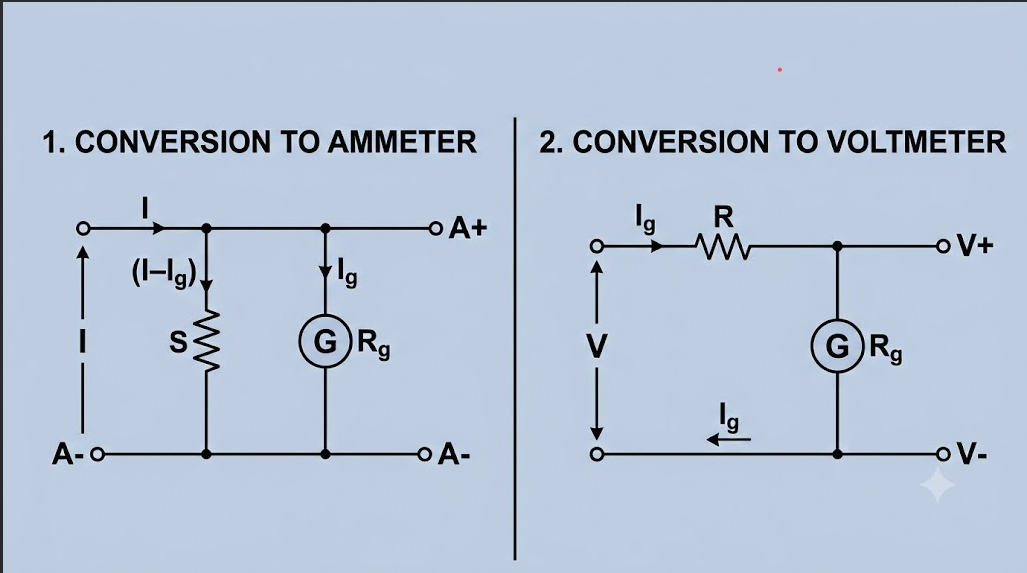
(a) Galvanometer → Ammeter (low resistance, in series)
An ammeter measures current and must be connected in series with the circuit element. To prevent it from disturbing the circuit, its effective resistance must be very small.
We connect a low-resistance shunt in parallel with the galvanometer of resistance and full-scale current . The shunt carries most of the current; only a tiny fraction goes through the galvanometer.
If is the total current and is the current through the galvanometer, then flows through the shunt. Since both have the same voltage across them:
The effective resistance of the ammeter is (since ) — very small, as required.
(b) Galvanometer → Voltmeter (high resistance, in parallel)
A voltmeter measures voltage and must be connected in parallel across a circuit element. To draw negligible current, its effective resistance must be very large.
We connect a high-resistance multiplier in series with the galvanometer. The galvanometer reaches its full-scale current only when the voltage across the series combination equals the voltmeter’s range :
The effective resistance of the voltmeter is — very large, as required.
[NEET Important] Memorise the placement: ammeter → shunt → parallel; voltmeter → multiplier → series. Reverse a connection and you can damage either the instrument or the circuit.
Memory Capsule
A compact recap to wrap up the chapter.
Construction
- Rectangular coil ( turns) on light frame.
- Curved (concave) pole pieces + soft iron core → radial field.
- Two phosphor-bronze ribbon springs → carry current and provide restoring torque.
- Pointer + scale.
Working
- Deflecting torque: (independent of angle, thanks to radial field).
- Restoring torque: .
- Equilibrium: — linear scale.
Sensitivity
| Quantity | Formula | Units |
|---|---|---|
| Current sensitivity | rad/A | |
| Voltage sensitivity | rad/V |
To increase sensitivity: .
Galvanometer → Ammeter
- Shunt in parallel.
- .
- Effective resistance ≈ (very low).
- Connected in series with the circuit element.
Galvanometer → Voltmeter
- Multiplier in series.
- .
- Effective resistance ≈ (very high).
- Connected in parallel with the circuit element.
A useful mnemonic
Ammeter — shunt — parallel;
Voltmeter — multiplier — series.
One-line takeaway
The galvanometer’s clever combination of a radial field, phosphor-bronze springs, and a torsion constant turns a current-driven torque into a linear deflection — and with the right resistor in parallel (shunt) or series (multiplier), the same coil becomes an ammeter or voltmeter.
Solved Examples
Example 1: Current sensitivity of a galvanometer
A moving coil galvanometer has 200 turns, each of area m. The magnetic field in the gap is 0.2 T and the torsional constant of the suspension is N·m/rad. Find the current sensitivity.
Solution. Formula:
Substitute , m, T, N·m/rad:
Answer: rad/A — i.e., a current of 1 mA gives a deflection of 6 rad.
Example 2: Voltage sensitivity
The galvanometer of Example 1 has coil resistance . Find its voltage sensitivity.
Solution.
Answer: rad/V.
Example 3: Converting to an ammeter (find the shunt)
A galvanometer of resistance gives full-scale deflection at mA. Find the shunt required to convert it into an ammeter of range 5 A.
Solution. Formula:
Substitute A, , A:
Answer: — a very low resistance, connected in parallel with the galvanometer.
Example 4: Converting to a voltmeter (find the multiplier)
The same galvanometer (, mA) is to be converted into a voltmeter of range 10 V. Find the multiplier resistance.
Solution. Formula:
Substitute V, A, :
Answer: — a very high resistance, connected in series with the galvanometer.
Example 5: Fraction of current through the galvanometer
In Example 3, what fraction of the total current passes through the galvanometer at full-scale deflection?
Solution. At full scale, mA and A.
Answer: — this is why the shunt protects the delicate galvanometer from large currents.
Example 6: Effective resistance of the converted ammeter
For the ammeter of Example 3, find the effective resistance.
Solution. Parallel combination:
Answer: — essentially equal to (since ). The very small effective resistance means inserting this ammeter in a circuit will barely change the current — exactly what we want.
Example 7: Effect of increasing the number of turns
If the number of turns of a galvanometer is doubled (everything else unchanged including suspension and magnet), how do (a) current sensitivity and (b) voltage sensitivity change?
Solution.
- (a) . Doubling doubles .
- (b) Coil resistance is proportional to the length of wire — doubling also approximately doubles . So
— unchanged.
Answer: Current sensitivity doubles; voltage sensitivity stays the same. This is the classic "sensitivity paradox" that JEE/NEET problems often probe.
Example 8: Multi-range conversion
A galvanometer of and mA is to be converted into (a) an ammeter of range 2 A and (b) a voltmeter of range 200 V. Find the required shunt and multiplier.
Solution.
(a) Ammeter:
(b) Voltmeter:
Answer: (a) Shunt in parallel; (b) Multiplier k in series.