
From Physics to Engineering: Sizing a Rope
Nine sections of theory, and now the payoff. Everything in this section is one question asked over and over: how big does this piece of metal have to be?
Start with the most concrete version of it. You are building a crane with a lifting capacity of 10 tonnes. How thick should the steel rope be?
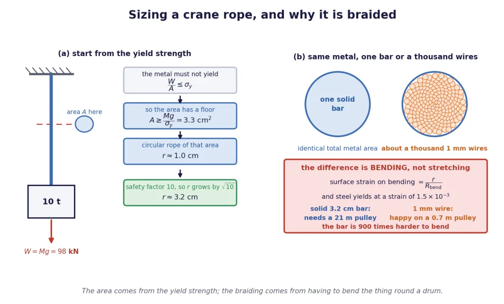
The design rule is a stress, not a force
Here is the move that turns physics into engineering. You do not design against the load. You design against the stress, because stress is what the material actually responds to.
And you do not design against the breaking stress either. You design against the yield strength — the stress at which the metal stops springing back and takes a permanent set. A crane rope that has stretched permanently is a ruined rope even though it did not snap.
A note on symbols. In this chapter a bare always means Poisson's ratio. A subscripted is a named material stress — the yield strength — in the same family as the used for longitudinal stress earlier. Elsewhere, stress is written .
Key Point — the sizing rule: The cross-sectional area has a floor set by the load and the yield strength. Anything thinner yields.
Doing the sum
Take tonnes kg, m/s, and a mild steel with a yield strength of Pa.
For a circular rope, , so
And then you multiply it by ten
That 1 cm is the answer to the question "what is the thinnest rope that does not yield under a perfectly steady 10-tonne load lowered gently onto a stationary hook".
That is not the question a crane asks. A crane's rope gets snatched, swung, shock-loaded when the load lifts off the ground, corroded, nicked, and worn. So engineers apply a factor of safety, and for lifting gear it is commonly a factor of about 10 on the load.
Key Point: Applying a safety factor to the load multiplies the required area by , and therefore multiplies the required radius by . A factor of 10 on the load costs only a factor of on the radius. Strength is cheap in this trade — which is exactly why the factors used are so generous.
At the rated load the working stress is MPa, a tenth of what the metal can take. The rope is loafing, and that is the point.
So why is it braided?
A 3.2 cm radius steel bar would carry the load beautifully. Nobody uses one. Real crane and lift ropes are braided from hundreds or thousands of fine wires, like a pigtail. Why go to that trouble?
Not for strength — the total metal area is the same either way, so the tensile capacity is identical. The reason is that a crane rope does not merely get pulled. It gets bent, round pulleys, every time it is used.
When a rod of radius is bent to a radius of curvature , the strain at its outer surface is
Steel with MPa yields at a strain of . Set and solve for the tightest pulley each option can survive:
| Option | Smallest pulley radius that keeps it elastic | |
|---|---|---|
| One solid bar | 3.2 cm | m |
| One fine wire | 1 mm | m |
A pulley 21 m in radius is not a pulley, it is a building. The solid bar is not a rope; it is a rigid rod that would take a permanent kink the first time it went over a drum. Cut the same metal into about a thousand 1 mm wires and every wire bends happily inside its elastic range.
There is a second, quantitative way to say the same thing. The resistance of a circular section to bending goes as . Replace one bar of radius by wires of radius carrying the same total area, and the bundle's bending resistance falls by a factor of — here 3.2 cm against 1 mm gives , so that factor is and the bundle is about a thousand times easier to bend for the same tensile strength.
Braiding also helps in two practical ways: fine wire is far easier to draw and handle than thick bar, and if one strand fails the rope does not, which a solid bar cannot offer.
[JEE Tip] "Why are ropes braided?" has a wrong answer that sounds right: "to make them stronger". They are not stronger. They have the same tensile strength and are dramatically more flexible, plus easier to manufacture and safer when a strand breaks.
[Board Important] The full crane-rope calculation — , find , apply the safety factor, explain the braiding — is a complete five-mark answer. Show the safety factor explicitly; it is worth a mark on its own.
Columns: Two Completely Different Ways to Fail
Turn the rope upside down. Instead of hanging a load from a wire, stand it on a pillar. The sizing rule looks identical:
and for a short, fat column that is the whole story: the material runs out of strength and gets crushed. Take a steel column carrying 50 tonnes, with MPa and m/s:
With a safety factor of 5 that becomes 98 cm, a square of side about 10 cm. Straightforward.
But a tall, slender column does not fail that way at all.
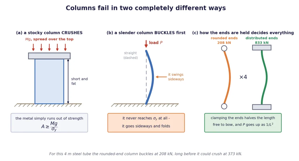
Buckling
Press down on a metre rule stood on its end. It does not crush. Long before the stress anywhere in it comes near the yield strength, it suddenly bows out sideways and folds.
Key Point — buckling:
Buckling is the sudden sideways collapse of a slender column under an axial compressive load, occurring at a stress far below the yield strength of the material. It is a failure of shape, not of material strength, and it is the reason is a necessary condition and not a sufficient one.
Why does it happen? Because a perfectly straight column is an idealisation. Any real column is a fraction of a millimetre off-centre somewhere. That tiny offset means the load has a small lever arm, which bends the column a little, which increases the lever arm, which bends it more. Below a critical load the column's own stiffness wins that race and the bow dies away. Above it, the bowing wins and runs away in an instant.
The critical load depends on the material's stiffness , on how the cross-section is arranged, and — very strongly — on length:
where is the length that is actually free to bow. Double the free length and you quarter the load the column can carry. Nothing else in this chapter is that brutal.
Why the ends matter so much
Now look at the third panel of the figure, and at the two columns in it.
- Rounded ends. The column sits on a rounded or pointed end that can pivot freely. The whole length is free to bow into a single arc, so .
- Distributed ends. The column is built into a broad flat cap and base, so the ends cannot rotate — they are forced to stay vertical. The bulge is squeezed into the middle, and the length that is effectively free to bow is only half the column: .
Since the critical load goes as , halving multiplies the load by four.
Key Point: A pillar with distributed (broad, built-in) ends carries about four times the load of an otherwise identical pillar with rounded ends. Nothing about the material changed. Only the boundary condition did.
Put real numbers on it. A steel tube 4 m long, outer radius 5 cm, wall 5 mm, with Pa and MPa:
| Failure mode | Load at which it happens |
|---|---|
| Crushing (material runs out of strength) | 373 kN |
| Buckling with rounded ends | 208 kN |
| Buckling with distributed ends | 833 kN |
Read that table carefully, because it contains the entire lesson.
With rounded ends the column buckles at 208 kN, long before it could ever reach the 373 kN needed to crush it. The yield strength of the steel is irrelevant; the column fails while the metal is still comfortably elastic. Change nothing but the end fittings, and the buckling load jumps to 833 kN — now above the crushing load, so the column finally fails the way said it would, at 373 kN.
The same column, the same steel, the same length: 208 kN or 373 kN, decided entirely by how you sat it down. That is why pillars are given broad capitals and broad bases, why scaffolding poles are clamped rather than merely rested, and why a column design must always be checked for buckling as well as for crushing.
[JEE Tip] If a question mentions a "long, slender" or "thin" column, or gives you a length-to-thickness ratio, buckling is the intended answer and the yield strength is a decoy. If it says "short" or "stocky", crushing is intended and length is the decoy.
[NEET Important] Two one-liners live here and both get asked: buckling is failure at a stress below the elastic limit, and a pillar with distributed ends carries more than one with rounded ends.
Beams: Three Design Lessons Hiding in One Formula
A beam is not a rope and not a column. It is loaded across its length, and it fails by sagging.
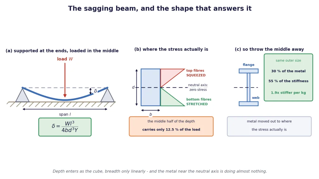
Take a bar of length , breadth and depth , resting on supports near its two ends and loaded at the centre with a weight . The sag at the middle, , is
Key Point — central sag of a supported beam: where is the span, the breadth (horizontal, across the load), the depth (vertical, in the direction of the load) and Young's modulus. Getting and the right way round is the whole examination.
Do not memorise this as a formula to plug into. Read it as four separate design instructions, and the differences between them are enormous.
Lesson one: depth is worth the cube
. Double the depth and the sag falls to one eighth.
Lesson two: breadth is worth only one power
. Double the breadth and the sag merely halves.
Put those two together and you get the most useful practical fact in this section. Take a wooden plank, 20 cm by 10 cm, and lay it flat: m, m. Now stand the same plank on its edge: m, m. Same plank, same wood, same amount of material.
Standing it on edge makes it four times stiffer. That is why every floor joist in every building you have ever walked on is tall and narrow rather than short and wide, and why a sheet of paper held flat flops while the same sheet folded into a channel does not.
Lesson three: the span is the enemy
. Halve the span and the sag falls by a factor of eight. Equivalently, doubling a bridge's span makes it sag eight times as much for the same load and the same beam — which is why long bridges are built as a series of short spans on piers, and why the ones that genuinely cross a long gap in one go are not beams at all but suspension or cable-stayed structures that work by tension instead.
Lesson four: the material helps, but only linearly
. Swap wood ( Pa) for steel ( Pa) and the sag drops by a factor of 20. Real, but note that it is only a factor of 20 for a completely different and far more expensive material, while merely turning your existing plank on its edge already bought you a factor of 4 for nothing.
The four lessons on one line
| Change | Effect on | Why |
|---|---|---|
| Double the depth | ||
| Double the breadth | ||
| Halve the span | ||
| Wood steel |
A worked number, to fix the scale
A steel beam of span 3 m, breadth 10 cm and depth 20 cm, loaded at its centre with 5000 N, with Pa:
About 0.21 mm. A fifth of a millimetre, under half a tonne, on a 3 m span. Steel beams are stiff, and beam sag calculations routinely come out in tenths of millimetres — if yours comes out in centimetres, you have almost certainly swapped and or dropped a power.
[JEE Tip] The most common single error in this formula is putting the wider dimension in as . is the dimension along the direction in which the load pushes — the vertical one for a horizontal beam. is the one across it. Draw the cross-section and mark the load arrow before you substitute.
[Board Important] "A beam of given material is to be made as stiff as possible. Should you increase its breadth or its depth?" — depth, because while . Quote both powers; the marks are for the comparison, not for the word.
Why Girders Are Shaped Like the Letter I
Lesson one said depth is worth the cube. So why not simply make every beam extremely deep and be done with it?
Two reasons, and the second one is the interesting one.
First, a very deep thin bar buckles sideways. Push down on a tall narrow beam and, exactly as with the slender column of the previous block, it can twist and flop over sideways rather than staying put and bending obediently. A bridge carrying moving traffic cannot guarantee the load lands exactly on the centreline, so a deep bar is a real risk.
Second, and more fundamental: most of the depth you add is not doing any work. To see why, look at what is actually going on inside a bent beam.
The stress inside a bending beam
When a beam sags, the two halves of it are doing opposite things:
- The top surface has to become shorter as the beam curves downwards. Those fibres are in compression.
- The bottom surface has to become longer. Those fibres are in tension.
- Somewhere in between there is a layer that neither stretches nor compresses. It is called the neutral axis, and for a symmetric section it runs through the centre.
The stress varies linearly across the depth: greatest at the two surfaces, and exactly zero at the neutral axis.
Key Point — the neutral axis:
In a bent beam the bending stress is zero on the neutral axis and rises linearly to a maximum at the top and bottom surfaces. The material sitting near the neutral axis is carrying almost no stress and is therefore contributing almost nothing to the beam's stiffness — while contributing its full share of the weight and the cost.
How little that middle material does
A beam's resistance to bending is governed by the quantity , where is the distance from the neutral axis. Because of the , material far from the axis counts for enormously more than material near it.
Take a solid rectangle of depth and slice out the middle half of the depth — the strip from to . That strip is 50% of the metal. How much of the bending resistance does it supply?
Key Point: In a rectangular beam, the middle half of the depth is half of the material but only 12.5% of the bending stiffness. The outer quarters — the other half of the material — supply the remaining 87.5%.
That single number is the entire argument for the I-section.
The I-section
So: keep the material at the top and the bottom, where the stress is largest and the leverage greatest, and take away most of the material near the neutral axis, where it was doing almost nothing.
- The two horizontal slabs are the flanges. They carry the compression and the tension.
- The thin vertical plate joining them is the web. It has one job — hold the flanges apart at the right depth (and carry the shear) — and it can be thin because the bending stress there is nearly zero anyway.
Compare a solid rectangular section 0.10 m by 0.20 m with an I-section inside exactly the same outer envelope, with 20 mm flanges and a 12 mm web:
| Section | Bending stiffness | Metal used | Stiffness per kilogram |
|---|---|---|---|
| Solid rectangle | 100% | 100% | 1.0 |
| I-section, same envelope | 55% | 30% | 1.9 |
The I-section keeps more than half the stiffness while using less than a third of the steel — so per kilogram of metal it is about 1.9 times as good. In a bridge, where the beam's own weight is a large part of what it has to carry, that ratio is what decides whether the design closes at all.
Key Point — why the I-section:
It puts material where the bending stress is largest (the flanges, far from the neutral axis) and removes it from where the stress is zero (near the axis). It buys a large load-bearing surface and enough depth to resist bending, while cutting the weight and the cost — and the extra breadth of the flanges also braces the beam against buckling sideways.
That is why every railway bridge, every steel-framed building and every crane jib you have ever looked at is full of I-shapes. It is not a manufacturing convenience. It is made visible.
[NEET Important] "Why are girders I-shaped?" — because the bending stress is largest at the top and bottom surfaces and zero at the neutral axis, so material is concentrated in the flanges and removed from the middle, giving the same strength for much less weight. That sentence is the full answer.
How Tall Can a Mountain Be?
The last application in this chapter is the most surprising, because it uses the elastic properties of rock to put a number on a piece of geography.
Why is the highest mountain on Earth about 9 km and not 90?
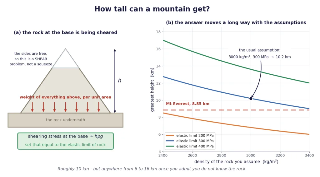
Setting it up
Picture a mountain of height and density sitting on the crust. The rock at the base has the whole weight of the mountain above it, and the force per unit area it feels is
the familiar , exactly as for a column of fluid.
Now the subtle part, and it is the part questions test. Is this a case of bulk compression? No — and the reason is that the sides of the mountain are free. There is nothing pushing inwards on the flanks. The rock at the base is being pressed down from above and is unsupported sideways, so it is being distorted, not uniformly squeezed. That is a shearing situation, and the relevant shear component is approximately itself.
Key Point: A mountain's base is not under uniform compression, because its sides are free. The rock there experiences a shearing stress of order , and the mountain can stand only while that stays below the elastic limit of rock. Push past it and the rock flows, and the mountain settles.
Getting the number
With the values usually quoted for crustal rock — an elastic limit of Pa and a density of kg/m — and taking m/s to keep the arithmetic clean:
Using m/s instead gives 10.2 km. Everest is 8.85 km. A one-line estimate, using nothing but the density of rock and a stress at which rock gives way, lands within about 15% of the tallest thing on the planet.
Being honest about what that 10 km is worth
Now the part most treatments skip, and it matters more than the answer.
is linear in both the assumed elastic limit and the assumed density. Neither of those is known to better than about a factor of two: "rock" covers granite, basalt, limestone and sandstone, with densities from roughly 2500 to 3300 kg/m and elastic limits that vary by more than that. So sweep them:
| (kg/m) | limit 200 MPa | limit 300 MPa | limit 400 MPa |
|---|---|---|---|
| 2500 | 8.2 km | 12.2 km | 16.3 km |
| 2700 | 7.6 km | 11.3 km | 15.1 km |
| 3000 | 6.8 km | 10.2 km | 13.6 km |
| 3300 | 6.2 km | 9.3 km | 12.4 km |
Computed from with m/s.
The plausible answers run from about 6 km to about 16 km. Everest, at 8.85 km, sits comfortably inside that band — but so would a mountain of 15 km.
Key Point: This calculation is an order-of-magnitude argument, and that is all it claims to be. It tells you that the limit is around ten kilometres rather than one or a hundred, and it tells you why: because rock has a finite elastic limit. It does not, and cannot, predict Everest's height to the nearest kilometre. Quote it as "about 10 km" and say what you assumed.
The check that makes it convincing
If the argument is right, then : the same rock on a world with weaker gravity should support a taller mountain.
Mars. Surface gravity 3.71 m/s, which is 2.64 times weaker than Earth's. The same rock should manage
The tallest mountain on Mars, Olympus Mons, is about 22 km. The prediction is right to within about 20%, on a different planet, from a one-line piece of Class 11 elasticity. That is the real test of the argument, and it passes.
A closing look around
Elasticity is quietly everywhere once you know what to look for.
Bones. The shaft of a human femur has a cross-section of roughly 3.3 cm and bone fails in compression at around 170 MPa, so it takes about N to crush it — the weight of nearly six tonnes. Bone is also, not coincidentally, a hollow tube with the material pushed to the outside: the same argument that gives you the I-section girder, arrived at by evolution a long time earlier.
Bridges. Every one of them is a negotiation between the four lessons of the previous block, the buckling limit on the columns, and the fatigue life from Section 9. Nothing is designed against one criterion alone.
Why steel. Compare the metals on the two numbers that matter:
| Metal | (Pa) | (Pa) | Yield strain |
|---|---|---|---|
| Steel | |||
| Brass | |||
| Aluminium | |||
| Copper |
Representative values; alloys of the same metal vary widely.
Steel wins on both counts at once — the highest Young's modulus, so it deforms least under load, and among the highest yield strengths, so it takes the most before deforming permanently. The same 10-tonne rope built in aluminium would need 10.3 cm of metal against steel's 3.3 cm. Add that steel is cheap, weldable and has a genuine fatigue endurance limit, and the choice makes itself.
[Board Important] The mountain-height derivation is a favourite. Three marks: identify the stress at the base as ; say explicitly that it is a shearing stress because the sides are free, not a bulk compression; equate it to the elastic limit of rock and solve. Losing the middle step loses the mark.
Solved Examples
Constants used throughout this section, unless a problem states otherwise: m/s; Pa; yield strength of mild steel Pa (a structural grade at Pa is used where the problem says so).
Example 1: Sizing a crane rope from scratch
A crane is to lift 10 tonnes. The steel available has a yield strength of Pa. Find (a) the minimum cross-sectional area of a circular rope, (b) the corresponding radius, and (c) the radius after applying a safety factor of 10 on the load.
Solution:
(a) The load and the area.
(b) The radius. For a circle, :
(c) With a safety factor of 10. The area must be ten times larger:
Note the scaling. . Ten times the strength cost only 3.16 times the radius.
Final Answer: (a) m; (b) about 1.0 cm; (c) about 3.2 cm.
Takeaway: A safety factor of on the load multiplies the area by and the radius only by . Strength is cheap in radius, which is exactly why engineers are so generous with it.
Example 2: Why not a single thick bar?
Take the 3.2 cm radius rope of Example 1. (a) If it is instead built from 1 mm radius wires, how many are needed for the same metal area? (b) Taking the yield strain of the steel as , find the smallest pulley radius that keeps a solid 3.2 cm bar elastic, and the smallest that keeps a 1 mm wire elastic. (c) Comment.
Solution:
(a) Counting the wires. Equal total area means about a thousand wires.
(b) The bend radius. Bending a rod of radius to a radius of curvature strains its surface by . Staying elastic requires
- Solid bar, m: m.
- Fine wire, m: m.
- (c) The comment. A 21 m radius pulley is absurd — a crane drum is well under a metre. The solid bar would take a permanent kink the first time it was wound on. The braided rope, made of the same metal in the same total quantity, bends round a 0.7 m drum entirely within its elastic range. Since the resistance to bending goes as , the bundle is roughly a thousand times easier to bend than the bar of the same total area.
Final Answer: (a) about 1040 wires; (b) 21 m for the bar, 0.67 m for a wire; (c) the bar cannot be used as a rope at all.
Takeaway: Braiding buys flexibility, not strength. The tensile capacity of the rope is set entirely by the total metal area; what changes is whether you can wind it round anything.
Example 3: Sizing a column, and then checking it
A steel column must carry 50 tonnes. Taking Pa, (a) find the minimum cross-sectional area on strength grounds, and (b) the area and the side of a square section after a safety factor of 5. (c) Is this calculation on its own enough to guarantee the column stands up?
Solution:
(a) The strength requirement.
(b) With a safety factor of 5.
(c) No. guards only against crushing — the material running out of strength. A slender column fails first by buckling, sideways, at a stress far below the yield strength. The buckling load depends on the length and on how the ends are held, neither of which appears anywhere in this calculation. The column must be checked separately against buckling, and for a tall column that check, not this one, is usually what decides the size.
Final Answer: (a) 19.6 cm; (b) 98 cm, a square of side about 9.9 cm; (c) no — buckling must be checked separately.
Takeaway: is necessary, never sufficient. It says nothing about length, and length is exactly what buckling cares about.
Example 4: The same column, sat down two different ways
A steel tube 4 m long has outer radius 5 cm and wall thickness 5 mm. Its crushing load is 373 kN. Its buckling load with freely pivoting (rounded) ends is 208 kN, and with built-in (distributed) ends the effective length that is free to bow is halved. Given that the buckling load varies as , (a) find the buckling load with distributed ends, and (b) state how the column actually fails in each case.
Solution:
(a) The end-condition factor. Building the ends in forces them to stay vertical, so the length free to bow drops from to . Since ,
(b) How it fails, case by case. A column fails by whichever mode has the lower load.
- Rounded ends: buckling at 208 kN against crushing at 373 kN. Buckling is lower, so the column buckles at 208 kN and never comes close to yielding. The strength of the steel is irrelevant here.
- Distributed ends: buckling at 833 kN against crushing at 373 kN. Now crushing is lower, so the column crushes at 373 kN, which is the answer the calculation predicted.
- Read the size of the effect. Changing nothing but the end fittings moved the failure load from 208 kN to 373 kN — an 80% gain, for no extra metal at all.
Final Answer: (a) 833 kN; (b) rounded ends buckle at 208 kN; distributed ends crush at 373 kN.
Takeaway: The failure load is the smaller of the crushing load and the buckling load, and only the buckling one knows about the ends. Broad capitals and broad bases on a pillar are worth more than a thicker pillar.
Example 5: A beam, with the units carried right through
A steel beam of span 3 m, breadth 10 cm and depth 20 cm is supported near its ends and loaded at the centre with 5000 N. Take Pa. Find the central sag.
Solution:
List everything in SI first, before touching the formula. N, m, m, m, Pa. Note that is the vertical dimension, the one along the load.
Substitute.
Numerator: .
Denominator, one factor at a time: ; ; .
Divide.
Final Answer: about 0.21 mm.
Takeaway: A beam sag in a Class 11 problem should come out in tenths of a millimetre. If your answer is in centimetres, check whether you have swapped and — that mistake alone changes this answer by a factor of four.
Example 6: Turning the plank on its edge
A wooden plank of rectangular cross-section 20 cm by 10 cm bridges a gap and is loaded at its centre. Compare the sag when it is laid flat (20 cm horizontal) with the sag when it is stood on edge (20 cm vertical). Which is stiffer, and by how much?
Solution:
- Identify and in each case. is always the vertical dimension.
- Flat: m, m.
- On edge: m, m.
Take the ratio, so that , and all cancel.
Or see it in one line. Swapping and changes the sag by .
Check with real numbers. For the steel beam of Example 5, flat gives 0.844 mm against 0.211 mm on edge. Ratio 4. It agrees.
Final Answer: Standing it on edge is 4 times stiffer — the same plank sags a quarter as much.
Takeaway: Rotating a beam through costs nothing and buys a factor of . That is why joists are tall and thin, and why nobody ever lays one flat on purpose.
Example 7: Three changes to a bridge beam
A beam sags by 4.0 mm under a given central load. Independently of one another, find the new sag if (a) the depth is doubled, (b) the breadth is doubled, (c) the span is halved, and (d) the material is changed from wood ( Pa) to steel ( Pa).
Solution:
Start from the powers. .
(a) Depth doubled. , so the sag is divided by :
(b) Breadth doubled. , so the sag is divided by 2:
(c) Span halved. , so the sag is multiplied by :
(d) Wood to steel. , and goes up by a factor of 20:
Final Answer: (a) 0.50 mm; (b) 2.0 mm; (c) 0.50 mm; (d) 0.20 mm.
Takeaway: Doubling the depth and halving the span are worth exactly the same — a factor of eight — while doubling the breadth is worth only two. Given a choice of one change, take the depth or the span every time.
Example 8: How much of a beam is doing nothing?
A beam has a solid rectangular cross-section of depth . Show that the middle half of the depth, which is half the material, provides only 12.5% of the resistance to bending. Use the fact that the resistance is proportional to , and hence explain the shape of an I-section girder.
Solution:
Set up. With breadth , a strip at distance from the neutral axis has area , so
Now only the middle half, from to . That is the same integral with in place of :
Take the ratio. while that strip is of the material.
The conclusion. Half the metal is producing an eighth of the stiffness, because the weighting makes material near the neutral axis nearly worthless. The outer quarters — the other half of the metal — supply 87.5%.
Hence the I-section. Keep the metal at the top and bottom, where is large and the bending stress is greatest, as two flanges; remove most of it from the middle, leaving only a thin web to hold the flanges apart at the right depth. A real I-section inside a 0.10 m by 0.20 m envelope keeps about 55% of the solid bar's stiffness using only about 30% of the metal — about 1.9 times the stiffness per kilogram.
Final Answer: The middle half of the depth is 50% of the material and 12.5% of the stiffness; removing most of it gives the I-section, which is roughly 1.9 times as stiff per kilogram.
Takeaway: The in is the whole reason girders are I-shaped. Distance from the neutral axis is rewarded quadratically, so material in the middle is being carried, not carrying.
Example 9: The height of the tallest possible mountain
The elastic limit of a typical rock is Pa and its density is kg/m. (a) Explain why the stress at the base of a mountain is a shearing stress rather than a bulk compression. (b) Estimate the greatest height a mountain of this rock could reach, using m/s. (c) Redo it with m/s and compare with Everest.
Solution:
(a) The nature of the stress. The rock at the base carries the weight of everything above it, so it is pressed downwards. But the sides of a mountain are free — no rock is pushing inwards on the flanks. Uniform compression from all sides would be a bulk (hydraulic) stress; here the loading is one-directional with the sides unsupported, so the rock is distorted rather than uniformly squeezed. That is shear, and the shear component is approximately itself.
(b) The estimate. The force per unit area at the base is Set that equal to the elastic limit:
(c) With m/s. Everest is 8.85 km — about 13% below this ceiling, which for a one-line estimate is a striking success.
Final Answer: (a) shear, because the sides are free; (b) 10 km; (c) 10.2 km, against Everest's 8.85 km.
Takeaway: Everest is not the height it is by accident. It is close to the tallest thing the elastic limit of rock will support on a planet with this much gravity.
Example 10: How much do you actually know that answer to?
Rock density plausibly ranges from 2500 to 3300 kg/m, and the elastic limit from about 200 to 400 MPa. (a) How does depend on each? (b) Find the extreme values of over those ranges, with m/s. (c) What should you say when you quote the answer?
Solution:
(a) The dependence. From , is directly proportional to the assumed elastic limit and inversely proportional to the assumed density. Both are first powers, so a 10% error in either produces about a 10% error in — no amplification, but no forgiveness either.
(b) The extremes.
- Tallest: biggest limit with lightest rock.
- Shortest: smallest limit with densest rock.
- (c) What to say. The honest statement is: "about 10 km, and anywhere from roughly 6 to 16 km depending on what you assume about the rock." Everest at 8.85 km lies inside that band, but so would a 15 km mountain, so the calculation confirms the scale of the limit and its cause — it does not predict Everest.
Final Answer: (a) and ; (b) 6.2 km to 16.3 km; (c) quote it as an order-of-magnitude result and state the assumptions.
Takeaway: An estimate without its error bar is not finished. The value of this argument is that it explains why there is a limit near 10 km, not that it pins the number down.
Example 11: The same rock on Mars
Mars has a surface gravity of 3.71 m/s. Using the same rock ( Pa, kg/m), (a) predict the greatest mountain height on Mars, (b) express it as a ratio to the Earth value, and (c) compare with Olympus Mons, which is about 22 km high.
Solution:
(a) Substitute.
(b) The ratio. Since with everything else fixed, and indeed .
(c) The comparison. Olympus Mons is about 22 km, against a predicted ceiling of 27 km. It sits below the limit, as it must, and within about 20% of it.
Why this matters. The argument was built on Earth and tested on another planet with a completely different gravity, using no adjustable parameters. That it works is far better evidence for the physics than the Earth number alone, which could always be explained away as a coincidence.
Final Answer: (a) about 27 km; (b) 2.64 times the Earth value; (c) Olympus Mons at 22 km sits just below it.
Takeaway: is the prediction that makes the argument testable, and the tallest mountain in the solar system is sitting on the planet with the weakest gravity of the two — exactly as it should be.
Example 12: Choosing the metal
Compare steel ( Pa, MPa) with aluminium ( Pa, MPa) for the 10-tonne crane rope of Example 1. (a) What area would each need? (b) Which stretches less at its own rated load? (c) Give two further reasons steel is chosen for heavy structures.
Solution:
- (a) Areas from , with N.
- Steel: m cm.
- Aluminium: m cm. The aluminium rope needs more than three times the cross-section.
- (b) Stretch at the rated load. At the yield point the strain is :
- Steel: .
- Aluminium: . These are close, so at the point of yielding the two stretch similarly. But at any given actual load, the steel rope is both thicker in capacity and made of a material three times stiffer, so it deforms far less in service.
- (c) Two further reasons.
- Fatigue. Steel has a genuine endurance limit — below roughly half its ultimate strength it survives an unlimited number of cycles. Aluminium has none, so an aluminium component has a finite life at any stress and must be replaced on schedule.
- Cost and workability. Steel is cheap per tonne, readily welded and rolled into I-sections, and its properties are extremely well characterised. For a structure whose own weight is not the binding constraint, that settles it.
Final Answer: (a) 3.27 cm steel against 10.3 cm aluminium; (b) steel deforms far less in service; (c) steel has a fatigue endurance limit and is cheap and weldable.
Takeaway: Steel wins on both numbers at once — the highest Young's modulus and among the highest yield strengths. Where weight is what matters rather than cost, aluminium comes back into the argument, which is why aircraft are aluminium and bridges are not.