
The Rod That Was Not Allowed to Grow
Heat a metal rod and it gets longer. You have known that since Class 9, and you know the rule:
where is the coefficient of linear expansion of the material and is the rise in temperature. Nothing here contradicts that. The question this section asks is different, and much sharper:
What happens if you heat the rod but refuse to let it get longer?
Bolt both ends of the rod between two immovable walls, then warm it. The rod still wants to expand by . It cannot. Something has to give — and what gives is the internal state of the metal. The rod ends up squeezed, carrying a real, measurable, sometimes destructive compressive stress that was created by nothing but a change of temperature. That is thermal stress.
A note on where this sits. Thermal stress, elastic hysteresis, elastic after-effect and elastic fatigue all sit outside the rationalised syllabus body text, and all of them are asked by Boards, JEE Main, JEE Advanced and NEET every single year. So they are developed here from first principles, with nothing assumed.
The derivation, in two honest steps
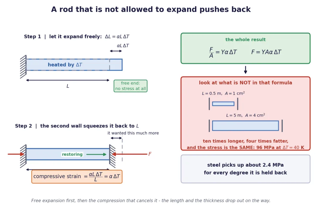
Do not try to do this in one line. Split it, exactly as the figure does.
Step 1 — let it expand freely. Pretend the second wall is not there. The rod, heated by , grows to a length . At this moment there is no stress at all — nothing is resisting anything.
Step 2 — now put the wall back and squash it. The wall must push the rod back from down to . That is a compression of exactly . Compressive strain is that compression divided by the length:
Step 3 — turn the strain into a stress with Young's modulus. From Section 4, stress strain, so
Key Point — thermal stress in a fully clamped rod: The stress is compressive if the rod is heated and prevented from expanding, and tensile if the rod is cooled and prevented from contracting. is Young's modulus, the coefficient of linear expansion, the magnitude of the temperature change.
A note on symbols, since is booked elsewhere. In this chapter always means Poisson's ratio, so thermal stress is written , or when a longitudinal-stress symbol is genuinely needed. Strain is throughout. If a book you own writes , that book is using for stress — check the convention before you copy a formula across.
The thing you must not miss
Look hard at and list what is not in it.
There is no . There is no .
Key Point: The thermal stress in a clamped rod is completely independent of the length of the rod and of its cross-sectional area. A 10 cm pin and a 25 m girder of the same steel, both rigidly clamped and both heated through the same , carry exactly the same stress. Only the material and the temperature change matter.
That is worth pausing over, because it is deeply counter-intuitive. A long rod expands more, yes — but it also needs proportionally more compression to squash it back, and the two effects cancel exactly. A thick rod needs a bigger force, yes — but it has proportionally more area to spread that force over, and again the two cancel.
The force does depend on . Stress does not; force does. Do not blur the two.
Feeling the size of it
For steel, Pa and per degree, so
Key Point — the number to carry in your head: Clamped steel picks up about 2.4 MPa of stress for every single degree it is prevented from expanding.
Now do the frightening arithmetic. Mild steel yields at roughly 250 MPa. Divide:
A temperature change of about a hundred degrees is enough to permanently deform fully clamped steel. Not to bend it, not to strain it a little — to take it past its yield point. A summer's day on a black steel bridge can swing the metal temperature by 40 degrees on its own.
[JEE Tip] The single most common error in this entire topic is putting a length or an area into the stress formula because the question generously supplied one. Questions supply and on purpose, to see whether you know they cancel. If the question asks for stress, ignore both. If it asks for force, you need but still not .
[Board Important] "Derive an expression for the thermal stress developed in a rod rigidly clamped at both ends" is a standard three-mark derivation. The marks are for the two steps: free expansion first, then the compression that cancels it. Write both.
What Engineers Actually Do About It
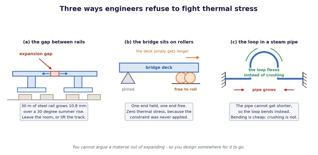
Here is the thing about : you cannot argue with any of the three factors. and belong to the material, and belongs to the weather. So engineers do not fight thermal stress at all. They remove the constraint that creates it.
Three classic answers
Railway lines are laid with gaps. A 30 m length of steel rail, warming by 30 degrees between a winter night and a summer afternoon, wants to grow by
So leave it about 11 mm of room at each joint and the rail expands into thin air, developing no stress at all. Weld the joints shut with no gap and the rail would instead pick up MPa of compression — enough, on a hot day, to make the track buckle sideways out of its bed. (Modern continuously welded track exists, but only because the rail is deliberately pre-stretched and pinned down hard enough to stop it going sideways — the stress is still there, it is just being contained on purpose.)
Bridges sit on rollers. One end of a bridge deck is pinned; the other rests on rollers or a slab of rubber-and-steel bearing. The deck lengthens and shortens with the seasons and simply slides. One end held, one end free, zero thermal stress — because the constraint was never applied.
Steam pipes carry expansion loops. A pipe run between two fixed anchors cannot get shorter, so a big U-shaped loop is welded into the middle. When the pipe grows, the loop flexes a little. Bending a pipe sideways takes almost nothing; crushing it lengthwise takes everything. That trade is the whole design.
When the supports give a little
Real walls are not infinitely rigid. Suppose the supports allow the rod to grow by a small amount , less than it wanted to. Then only the leftover expansion has to be squeezed out:
Key Point — partially yielding supports: Note that and have come back into the problem. The clean independence of the previous block belongs to the fully clamped case only. And if , the rod never touches the far wall and the stress is zero.
The trick that makes reinforced concrete possible
One more consequence, and it is a beautiful one. Concrete has per degree. Steel has per degree. They are the same, to two figures.
That is not a coincidence anybody engineered — it is a lucky fact about the two materials — but it is the reason reinforced concrete works at all. A steel bar embedded in concrete is completely constrained by the concrete around it, so if the two expanded at different rates, every seasonal temperature swing would build up stress at the interface and crack the concrete off the bar within a few years. Because the two coefficients match, the pair expand together and nothing happens.
Which metal is worst?
The product decides everything, and it is not simply "the metal that expands the most":
| Material | (Pa) | (per degree) | Stress per degree (MPa) |
|---|---|---|---|
| Steel | 2.40 | ||
| Copper | 2.04 | ||
| Brass | 1.73 | ||
| Aluminium | 1.61 | ||
| Invar (an iron-nickel alloy) | 0.17 |
Representative values; different grades of the same metal vary by a few per cent.
Read the table carefully. Aluminium expands almost twice as much as steel and yet develops a smaller thermal stress, because it is so much less stiff that it gives way instead of pushing back. And Invar, which barely expands at all, is what precision instruments and old surveying tapes are made of.
[NEET Important] "Which of these develops the greatest thermal stress?" is a standard single-line question, and the answer is never "whichever has the largest ". Multiply by and compare the products.
[Board Important] Be ready to explain in words why gaps are left between rails and why bridges rest on rollers. Two marks, and the answer is "to allow free thermal expansion so that no thermal stress develops" — not "so the metal does not get hot".
Two Materials Sharing One Constraint
Now the version that JEE actually asks. Take two different materials and force them to obey a single geometric condition. There are exactly two ways to do this, and telling them apart is the whole skill.
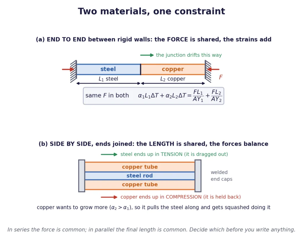
Case 1 — end to end between rigid walls (in series)
Two rods, lengths and , Young's moduli and , expansion coefficients and , joined at a junction and clamped between two immovable walls. Heat the whole thing by .
What is common here is the force. The junction is in equilibrium, so whatever push the first rod feels, the second feels the same. What is not common is the strain — the two rods squash by different amounts.
The condition is that the total length does not change. Rod 1 would grow by and rod 2 by ; between them the force must compress them by exactly that much in total:
Key Point — composite rod in series: and the stress in both rods is the same, , because they share both the force and (here) the area.
And the junction moves. Each rod individually does not end up at its original length — only the total is fixed. The junction slides towards whichever material wanted to expand more. That displacement is a favourite follow-up part, and you get it by working out the net change of just one rod:
Case 2 — side by side, ends joined (in parallel)
A steel rod running down the middle of a copper tube, both the same length, welded to the same end caps. Heat the assembly.
What is common here is the final length. Both pieces must end up exactly as long as each other, because they are bolted together at both ends. What is not common is the force.
Copper has the bigger , so left alone the copper would end up longer. It cannot. So the copper drags the steel out beyond where the steel wanted to be, and the steel holds the copper back from where the copper wanted to be. The steel ends up in tension and the copper in compression, with equal and opposite forces because nothing external is pulling on the assembly.
Key Point — composite rod in parallel:
Force balance: (one tensile, one compressive).
Compatibility, with material 2 the one that expands more: and the common final strain is the -weighted average of the two free expansions:
Notice the difference in the numerators. In series it is the sum that drives the force; in parallel it is the difference . If two parallel materials had the same , no force would develop at all — which is exactly the reinforced-concrete story from the previous block, seen from the other side.
How to tell which case you are in, in five seconds
| Ask yourself | Series | Parallel |
|---|---|---|
| Are the pieces one after the other, or side by side? | one after the other | side by side |
| What is shared? | the force | the final length |
| What adds up? | the length changes | the forces (to zero) |
| Driven by | ||
| If both materials were identical | stress is still | stress is zero |
That last row is the fastest sanity check there is. Set the two materials equal in your final expression: the series answer must collapse back to , and the parallel answer must collapse to zero. If yours does not, you have made an algebra slip.
[JEE Tip] Advanced likes to hide a parallel problem inside a picture that looks like a series one — a rod inside a tube drawn end-on, or two wires holding a rigid bar. Ignore the picture and ask the two questions: what is forced to be the same, and what is forced to add up. That decides the equations, not the drawing.
The Loop That Does Not Close: Elastic Hysteresis
Everything so far in this chapter has quietly assumed something that is not true: that a material's stress depends only on its current strain. Load a wire to a strain of and the stress is whatever the curve says at — the same whether you got there by loading up or by unloading down.
For a rubber band, that is simply false.
What the loop is
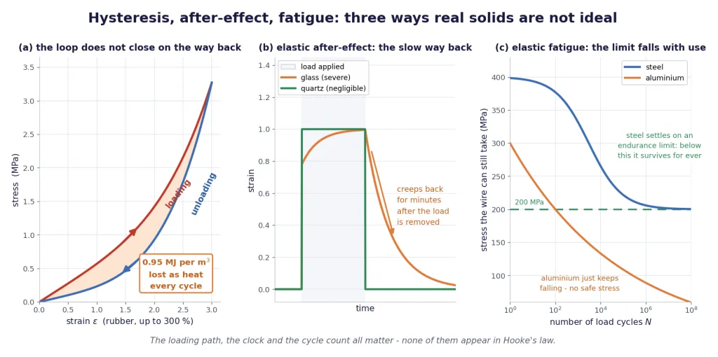
Stretch a rubber strip slowly, all the way out, plotting stress against strain as you go. Then let it back slowly, plotting again. The return curve does not retrace the outward one. It lies below it, everywhere. The two curves meet only at the two ends, where the strain is zero and where the strain is a maximum, and in between they enclose an area.
Key Point — elastic hysteresis:
Elastic hysteresis is the failure of the loading and unloading stress-strain curves of a material to coincide. The strain at any moment depends not only on the stress now but on the history of how the material was loaded. The closed figure traced out over one full load-and-unload cycle is called the hysteresis loop.
The rubber does come all the way back to its original length — no permanent set, this is not plasticity. It is still fully elastic. It just takes a different road home.
The area is energy, and the energy is heat
From Section 8 you know that the area under a stress-strain curve is the energy per unit volume. Apply that to both branches.
- Going up the loading curve, you do work on the rubber. The area under the loading curve is the energy you put in, per cubic metre.
- Coming down the unloading curve, the rubber does work on you. The area under the unloading curve is the energy you get back, per cubic metre.
The unloading curve is lower, so you get back less than you put in. The difference is the area trapped between the two curves.
Key Point — the loop area: That energy is not stored and not returned. It is dissipated inside the material as heat. A material with a fat loop is a good energy absorber; a material with a thin loop is a good spring.
For the rubber loop drawn in the figure — stretched to a strain of 3, that is to four times its length — the numbers work out as: 3.45 MJ per cubic metre put in on the way up, 2.50 MJ per cubic metre returned on the way down, and so 0.95 MJ per cubic metre lost as heat in each cycle, which is 27% of everything you supplied.
That is why a rubber band gets noticeably warm if you stretch and release it fast, twenty or thirty times in a row. Try it. The heat is the loop area, made real.
Designing to exploit it
Most of the time, energy dissipation is a nuisance. In two very familiar places, it is the entire point.
Shock absorbers and engine mounts. A car hits a pothole. The wheel is thrown upward and the energy has to go somewhere. If the suspension were a perfect spring — thin loop, no losses — the energy would just be given straight back and the car would bounce, and bounce, and bounce. You want the energy removed from the system, converted to heat and radiated away. So the rubber bushes and dampers are chosen for a large hysteresis loop. Every bump is a lap of the loop, and every lap turns a slug of energy into a little bit of warmth.
Car tyres. Here the calculation is finer. Every revolution, the piece of tread entering the contact patch is squashed flat and then released — one full loop of the hysteresis cycle for that piece of rubber. You need enough hysteresis for grip and for a comfortable ride, but every joule that goes round the loop comes out of your fuel tank. This is rolling resistance, and it is why an under-inflated tyre is worse for mileage: a softer tyre flexes more, sweeps out a bigger loop each turn, and burns more fuel as heat in the sidewalls. It is also why tyres get hot on a motorway and why a badly under-inflated one can get hot enough to fail.
Key Point: A shock absorber and a car tyre are the same physics with opposite sign conventions. In the shock absorber the dissipated energy is what you are paying for. In the tyre it is what you are paying.
[JEE Tip] If a question gives you a loading curve and an unloading curve and asks for "the energy dissipated", it wants the area between them, not the area under either one. If it asks for "the work done on the material", that is the area under the loading curve alone. Read which one is being asked.
Two More Ways a Real Solid Misbehaves
Hysteresis said that the path matters. The next two effects say that the clock matters and the count matters.
Elastic after-effect: the slow way back
Take the load off a stretched wire and, in the ideal picture, it snaps back to its original length instantly. Real materials often do not. They come back most of the way at once, and then keep creeping back for seconds, minutes, sometimes hours.
Key Point — elastic after-effect:
The elastic after-effect is the delay between removing the deforming force and the body's complete return to its original shape. The body does get all the way back — this is not a permanent set — it simply takes time about it.
The size of the effect depends enormously on the material, and the two extremes are worth memorising:
- Quartz fibre (and phosphor bronze) — the after-effect is negligible. Remove the twist and the fibre is back where it started, essentially instantly.
- Glass — the after-effect is severe. A glass fibre twisted and released can take hours to fully recover its original position.
That contrast is not a curiosity, it is a design rule. The suspension fibre in a moving-coil galvanometer, in a torsion balance, in any instrument that measures a tiny force by how far something twists, is made of quartz — because if it were glass, the needle would still be drifting back towards zero long after the current had been switched off, and every reading would depend on what you measured half an hour ago.
Elastic fatigue: the slow loss of strength
Now cycle a material instead of loading it once.
Key Point — elastic fatigue:
Elastic fatigue is the loss of elastic strength suffered by a material subjected to repeated cycles of stress. A specimen that comfortably survives a given stress once can fail at that same stress after enough repetitions.
Take a piece of wire and bend it back and forth with your fingers. Bend it once and it springs back. Bend it twenty times in the same place and it snaps. Nothing about the force you applied changed — you were not pulling harder on the twentieth bend than on the first. What changed is the wire. Each cycle drives microscopic slip along the crystal planes at the surface, tiny cracks nucleate there, and each subsequent cycle drives them a little deeper until what is left cannot carry the load.
Notice why bending is so effective at this. The strain at the surface of a bent wire of radius curled to a radius of curvature is
Fold a 0.4 mm wire round a 2 mm radius and the surface strain is , that is 20% — when steel yields at a strain of about , one part in eight hundred. Your fingers are driving the surface of that wire deep into the plastic region, twice per bend, and the surface is where fatigue cracks live.
The engineering version
Fatigue is why every serious structure is rated for a number of cycles, not just for a load.
- A bridge carrying 4000 vehicles a day, each one loading and then unloading the deck, sees about 8000 cycles a day — which is cycles in about 3.4 years. Aircraft are retired on flight-cycle counts for exactly this reason; a short-haul aircraft ages faster than a long-haul one that has flown the same number of hours.
- Steel has an endurance limit. Below roughly half its ultimate tensile strength, a steel component survives an unlimited number of cycles. Design under that line and fatigue is simply not your problem.
- Aluminium does not. Its fatigue curve keeps falling with no floor, so an aluminium part has a finite life at any stress at all, and must be given a scheduled replacement interval. This distinction, visible as the flat line and the falling line in the figure above, drives a great deal of real engineering practice.
Putting the three together
| Effect | What it says | Where you meet it |
|---|---|---|
| Hysteresis | the loading and unloading curves differ; the loop area is heat per cycle | shock absorbers, tyres, engine mounts |
| Elastic after-effect | the return to the original shape is delayed in time | quartz fibres in instruments; glass is the bad case |
| Elastic fatigue | elastic strength falls with the number of cycles | a wire snapping after repeated bends; bridges and aircraft rated in cycles |
The four traps in this section
- Putting or into the thermal stress. They cancel in the fully clamped case. They come back the moment the supports yield by a finite amount.
- Confusing hysteresis with plastic deformation. Hysteresis is fully elastic — the material returns to its original length. It just dissipates energy on the way.
- Confusing the after-effect with a permanent set. After-effect: gets there eventually. Permanent set: never gets there.
- Treating fatigue as damage from overloading. Fatigue happens at stresses well below the elastic limit. The stress never had to be large; it only had to be repeated.
[NEET Important] All five definitions in this section — thermal stress, hysteresis, the loop area as energy, elastic after-effect, elastic fatigue — are prime one-line recall questions. Learn the sentence, not just the idea.
Solved Examples
Constants used throughout this section, unless a problem states otherwise:
| Material | (Pa) | (per degree) |
|---|---|---|
| Steel | ||
| Copper | ||
| Brass | ||
| Aluminium |
Where a value of is needed it is m/s, and it is stated in the problem that uses it.
Example 1: The standard clamped rod, start to finish
A steel rod 1 m long with a cross-sectional area of 1 cm is clamped rigidly between two immovable walls at 20 °C. It is then heated to 60 °C. Find (a) how much it would have expanded if it had been free, (b) the compressive strain it actually develops, (c) the thermal stress, and (d) the force it exerts on each wall.
Solution:
(a) Free expansion. degrees.
(b) The strain. The walls squeeze that entire expansion back out, so the compressive strain is
(c) The stress, from :
(d) The force. Now, and only now, does the area enter. cm m.
Final Answer: (a) 0.48 mm; (b) , compressive; (c) 96 MPa, compressive; (d) 9.6 kN.
Takeaway: Half a millimetre of thwarted expansion is worth nearly a tonne of force. Strains this small produce stresses this large because for steel is enormous — that is what a big Young's modulus means.
Example 2: Does a bigger rod develop a bigger stress?
Repeat Example 1 for a steel rod 5 m long with an area of 4 cm, heated through the same 40 degrees. Compare the free expansion, the stress and the force with the previous answers.
Solution:
Free expansion — this one does scale with length: five times more than before, exactly as you would expect.
Strain. But the rod is also five times longer, so identical. The extra expansion is spread over extra length and the fraction is unchanged.
Stress. identical to Example 1, even though this rod is ten times longer and four times fatter.
Force. With m: four times the earlier force — because the area is four times as large.
Final Answer: Free expansion 2.4 mm (5 times more); stress 96 MPa (the same); force 38.4 kN (4 times more).
Takeaway: Stress is independent of both and ; force is proportional to . Every number a thermal-stress question gives you is either load-bearing or bait, and the two lengths and the area are usually bait.
Example 3: Sizing the gap between two rails
Steel rails are laid in 30 m lengths at 15 °C. The hottest the rail metal is expected to get is 45 °C. (a) What gap must be left at each joint? (b) If a careless contractor leaves no gap at all, what compressive stress will build up on the hottest day, and what force would a rail of cross-section 50 cm then push against its neighbour with?
Solution:
(a) The gap. degrees. So leave about 11 mm, and the rail expands into the gap with no stress at all.
(b) With no gap, the joint acts as a rigid wall and the whole expansion is squeezed out:
The force, with cm m: about the weight of 37 tonnes, pushing sideways along a track that is only held down by ballast.
Final Answer: (a) about 11 mm; (b) 72 MPa and 360 kN.
Takeaway: The gap is not about the metal getting hot, it is about the metal having somewhere to go. A rail with nowhere to go buckles out of its bed sideways, because sideways is the only direction left.
Example 4: Supports that give a little
A steel rod of length 2 m and cross-section 4 cm is fixed between two supports at 20 °C and heated to 70 °C. The supports are not perfectly rigid and yield by a total of 0.5 mm. Find the stress in the rod and the force on the supports. What would the answers be if the rod had been only 0.5 m long?
Solution:
Free expansion. degrees.
How much has to be squeezed out. The supports absorb 0.5 mm of it, so only has to be taken up by compressing the rod.
Strain and stress.
Force. N kN.
Now the 0.5 m rod. Its free expansion is only m mm — less than the 0.5 mm the supports give. The rod never reaches the far support at all.
Final Answer: 70 MPa and 28 kN for the 2 m rod; zero stress and zero force for the 0.5 m rod.
Takeaway: The moment the supports yield by a fixed amount, length matters again. Always compare with the yield first — if the yield wins, the answer is zero and there is no calculation to do.
Example 5: A wire that is cooled instead of heated
A steel wire of cross-section 0.8 mm is stretched taut between two rigid clamps at 40 °C, with no initial tension. It is then cooled to 10 °C. (a) What is the stress in it, and is it tensile or compressive? (b) What is the tension? (c) If the breaking stress of this steel is Pa, by how much would you have to cool it to snap it?
Solution:
(a) Direction first. Cooling makes the wire want to contract. The clamps will not let it, so they hold it stretched: the stress is tensile. The magnitude does not care about the sign of :
(b) The tension. mm m. about the weight of a 6 kg mass, hanging on a wire thinner than a paper clip, produced by nothing but a cool night.
(c) The temperature drop that breaks it. Set the stress equal to the breaking stress:
Final Answer: (a) Pa, tensile; (b) 57.6 N; (c) a drop of about 167 degrees.
Takeaway: Heated and clamped means compression; cooled and clamped means tension. Decide the sign from the physics in one sentence before you touch the algebra, because the formula gives you only the size.
Example 6: Two rods end to end between rigid walls
A steel rod 0.5 m long and a copper rod 0.5 m long, each of cross-section 2 cm, are joined end to end and clamped between two immovable walls at 20 °C. The assembly is heated to 60 °C. Find (a) the force on the walls, (b) the stress in each rod, and (c) how far the junction between them moves, and in which direction.
Solution:
Identify the case. The rods are one after the other, so this is series: the force is common and the length changes must cancel.
(a) Write the compatibility condition. With degrees, the total free expansion must equal the total compression:
Left-hand side.
Right-hand side, with m:
Solve.
(b) The stress, the same in both rods since they share and :
(c) The junction. Take the steel rod alone: it expands freely by m and is compressed by m. Net: positive, so the steel end grows a little and pushes the junction towards the copper.
Check. Do the same for the copper: free , compressed , net m. The two net changes cancel exactly, as they must.
Final Answer: (a) 17.4 kN; (b) 87 MPa in both; (c) 0.0225 mm, towards the copper end.
Takeaway: The junction moves towards whichever material wanted to expand more. Computing that displacement from each rod separately and checking that the two cancel is the free error-check this problem hands you — use it.
Example 7: A steel rod inside a copper tube
A steel rod and a copper tube, both 1 m long and each of cross-sectional area 1 cm, are rigidly joined to the same end caps at both ends. The assembly is heated through 100 degrees. Find the force in each, the stress in each, and the final strain of the assembly.
Solution:
Identify the case. Side by side, joined at both ends, so this is parallel: the final length is common and the forces must balance.
Who pulls whom. is larger than , so left alone the copper would be longer. It gets held back — copper in compression, steel in tension.
Compatibility. Both must reach the same final strain :
Rearrange and substitute. With m and :
The stresses. Same area for both, so both come to tensile in the steel, compressive in the copper.
The final strain, from the steel side: and from the copper side: . They agree.
Final Answer: 3750 N in each; 37.5 MPa tensile in the steel and 37.5 MPa compressive in the copper; common strain .
Takeaway: The assembly settles at a strain between the two free values, weighted by — closer to whichever member is stiffer or fatter. If both materials had the same the force would have been exactly zero, which is your instant sanity check.
Example 8: Which metal is the troublemaker?
Four rods — steel, copper, brass and aluminium — are each clamped between rigid walls and heated through the same 50 degrees. Rank them by the thermal stress developed. Aluminium has the largest expansion coefficient of the four: does it win?
Solution:
The quantity that decides it is the product , not alone.
Compute each stress, using with :
| Material | (Pa per degree) | Stress at |
|---|---|---|
| Steel | Pa | |
| Copper | Pa | |
| Brass | Pa | |
| Aluminium | Pa |
Read the ranking. Steel copper brass aluminium.
Answer the question. No, aluminium does not win. It expands roughly twice as much as steel, but its Young's modulus is only about a third of steel's, and the modulus wins the argument. Aluminium is soft enough that it gives way rather than pushing back.
Final Answer: Steel develops the largest thermal stress, 120 MPa; aluminium the smallest, 81 MPa, despite having the largest .
Takeaway: Thermal stress is a contest between how much a material wants to move and how hard it is to stop it moving. A material that expands enthusiastically but yields easily is not dangerous; steel, which barely expands but refuses to be squashed, is.
Example 9: Reading energy off a hysteresis loop
A rubber block is taken through a full stretch-and-release cycle. Measurement of the two curves gives the work done on the rubber during loading as J per cubic metre, and the work recovered from it during unloading as J per cubic metre. (a) What is the area of the hysteresis loop? (b) What fraction of the input energy is lost? (c) A rubber bush of volume 120 cm in a car's suspension goes round this loop twice a second on a rough road. At what rate is it generating heat, and how much heat is that over an hour?
Solution:
(a) The loop area. The area under the loading curve is what went in; the area under the unloading curve is what came back; the area between them is the difference.
(b) The fraction.
(c) The power. Volume cm m, frequency 2 per second.
Over an hour.
Final Answer: (a) J/m; (b) about 27.5%; (c) about 228 W, roughly 820 kJ in an hour.
Takeaway: A rubber bush the size of a matchbox is a 200-watt heater when the road is bad — and that is exactly what you want it to be, because every one of those watts is energy taken out of the bouncing car.
Example 10: Where a tyre's fuel goes
Each revolution, a car tyre's tread does 480 J of work on the rubber in the contact patch and gets 350 J of it back. The tyre has an outer radius of 0.31 m and the car is travelling at 60 km/h. (a) How much energy is dissipated per revolution? (b) How many revolutions per second? (c) At what rate is that one tyre turning fuel into heat?
Solution:
(a) Per revolution.
(b) Revolutions per second. First convert the speed: km/h m/s. The circumference is m.
(c) The power.
What that means. Multiply by four tyres and you are burning something like 4.5 kW purely on flexing rubber — a serious fraction of what a small engine produces at cruising speed. This is rolling resistance, and it is all hysteresis loop.
Final Answer: (a) 130 J; (b) 8.56 per second; (c) about 1.1 kW per tyre.
Takeaway: An under-inflated tyre flexes further, sweeps a bigger loop, and burns more fuel — and gets hotter doing it. The tyre-pressure sticker inside your car door is a hysteresis-loop specification in disguise.
Example 11: Choosing the fibre for an instrument
A sensitive torsion balance measures a tiny force by how far a suspended fibre twists. Two fibres are available: quartz and glass. Explain, using the elastic after-effect, which one must be used and what would go wrong with the other. If the instrument is read once a minute, roughly what property of the fibre decides whether that reading rate is usable?
Solution:
State the effect. The elastic after-effect is the delay between removing the deforming force and the body completely regaining its original shape. The body does get all the way back; it simply takes time.
Compare the two materials. In quartz the after-effect is negligible — release the twist and the fibre is back at zero essentially at once. In glass it is severe — a twisted glass fibre can take hours to fully recover.
What goes wrong with glass. Suppose you measure a large force, then remove it and immediately measure a small one. The glass fibre is still slowly untwisting from the previous reading, so the pointer position you read is the new deflection plus whatever is left of the old one. Every reading would be contaminated by the history of the instrument, and the size of the error would depend on how long ago the last measurement was. The instrument would not be wrong by a fixed amount you could correct for — it would be unrepeatable, which is worse.
What decides the usable reading rate. The recovery time of the fibre after the load is removed. It must be short compared with the interval between readings. Reading once a minute needs a fibre whose after-effect dies away in a few seconds — quartz easily; glass not at all.
Final Answer: Quartz, because its elastic after-effect is negligible. A glass fibre would still be creeping back from the previous measurement, so readings would depend on the instrument's recent history. The recovery time must be much shorter than the interval between readings.
Takeaway: "It gets back eventually" is not good enough for an instrument. Ordinary elasticity theory has no clock in it at all, and the after-effect is the reminder that real materials do.
Example 12: Why the wire snaps, and when the bridge is old
(a) A steel wire of radius 0.4 mm is bent back and forth by hand, each bend curling it to a radius of curvature of about 2 mm. Estimate the strain at the wire's surface and compare it with the yield strain of steel, taking the yield stress as 250 MPa. Explain why the wire eventually snaps even though you never pull harder. (b) A bridge girder registers about 8000 stress cycles a day — roughly 4000 vehicles, each producing two stress reversals as it approaches and then leaves the span. Steel is usually treated as safe below about cycles at working stress. After how many years does this bridge reach that count?
Solution:
(a) The surface strain of a bent wire. When a rod of radius is bent to a radius of curvature , the outer surface is stretched by that is 20%.
Compare with the yield strain. The bending strain is about 160 times the yield strain.
Why it snaps. Each bend drives the surface layer far into the plastic region, first one way then the other. Microscopic slip steps form at the surface, cracks nucleate there and grow a little deeper on every cycle. This is elastic fatigue: the wire is losing its strength cycle by cycle, and eventually what is left of the cross-section cannot carry even a gentle pull. The force you applied never increased — the wire's capacity decreased.
(b) The cycle count. At 8000 cycles a day,
Final Answer: (a) surface strain 0.20, about 160 times the yield strain of ; the wire fails by fatigue. (b) about 3.4 years.
Takeaway: Fatigue is not about how hard, it is about how often. A structure can be perfectly safe against a single application of a load and still have a finite life measured in cycles — which is why bridges and aircraft are retired on counts, not on strength tests.