
What JEE Adds to This Chapter
Sections 1 to 11 built elasticity properly, and that build is complete for the Board syllabus. What JEE adds is not harder physics — it is the same three moduli — but a family of set-ups where the quantity you need is not constant along the object, so you cannot simply write and stop.
A rod that is thicker at one end than the other. A wire hanging under its own weight, where the tension at the top is not the tension at the bottom. A rod spun about one end, where the tension dies away to nothing at the far tip. A rigid bar resting on three wires that must all end up on one straight line. A composite rod squeezed between two walls that will not move. A mass dropped onto a wire instead of lowered onto it.
Every one of them is answered the same way: stop treating the object as a single thing, slice it, and add up the slices.
Most of what follows sits outside the rationalised syllabus body text, but JEE Main and JEE Advanced ask it every year, so it is developed here from first principles.
The nine things this section teaches
| # | Skill | Why it earns marks |
|---|---|---|
| 1 | Elongation of a non-uniform bar by integration — tapering, conical, varying width | The examiner picks a shape with no formula. You build one |
| 2 | A heavy wire under its own weight, and the cone that is exactly one third of it | The tension varies, so the strain varies |
| 3 | A rod spun about an end or a centre | Tension is largest at the axis and zero at the tip |
| 4 | Series and parallel wires, treated as springs of constant | Two lines instead of two pages |
| 5 | The rigid bar on several wires — force balance, torque balance, compatibility | Three equations, always the same three |
| 6 | Thermal stress in a composite rod and in a bimetallic strip | The one place two materials must be solved together |
| 7 | Strain energy, energy released on fracture, and the dropped mass | The extension comes out at exactly twice the static one |
| 8 | Extension that changes with the state of motion — lifts, vertical circles | The wire does not change; the tension does |
| 9 | Torsion in depth — the couple by integration, hollow shafts, the torsional pendulum | makes this the most sensitive formula in the chapter |
Running underneath all nine is a single habit: before writing any formula, ask whether the force, the area, or both, are the same everywhere along the object. If either varies, you integrate. If two bodies share one constraint, you write a compatibility equation. Nothing else in this section is difficult.
Conventions, fixed now
Symbols. denotes Poisson's ratio throughout. Stress is written wherever possible, and where a symbol is unavoidable it is , and for longitudinal, shearing and hydraulic stress. Strain is . The moduli are (Young's), (shear) and (bulk), with compressibility . Elsewhere often denotes stress, with or for Poisson's ratio — check the convention before copying a formula out of anything.
Careful: does double duty in this section, as the compressibility and as the force constant of a wire treated as a spring. They never appear in the same problem, and every use below says which one it is.
Constants. Unless a problem states otherwise: Pa, Pa, Pa, Pa, Pa, Pa, kg/m, per degree, per degree, per degree. Every problem states which constants it used, and no problem mixes with .
Key Point — the master equation of this whole section: Everything else is a special case. Constant and constant collapses it to . A varying area gives you the tapering-bar family. A varying force gives you the self-weight and rotating-rod family. Write this line first and you can never be lost.
[Exam Tip] Three questions, asked before any algebra, decide almost every problem below. Is the force the same at every cross-section? Is the area the same at every cross-section? Do two or more bodies have to fit together at the end? A "no" to the first two means integrate; a "yes" to the third means write a compatibility equation. Answer all three and the method is chosen before you have written a symbol.
Non-Uniform Bars: Slice, Stretch, Add
The formula has one silent assumption buried in it: that every cross-section of the bar carries the same force over the same area, and therefore suffers the same strain. Break either half of that and the formula is simply wrong.
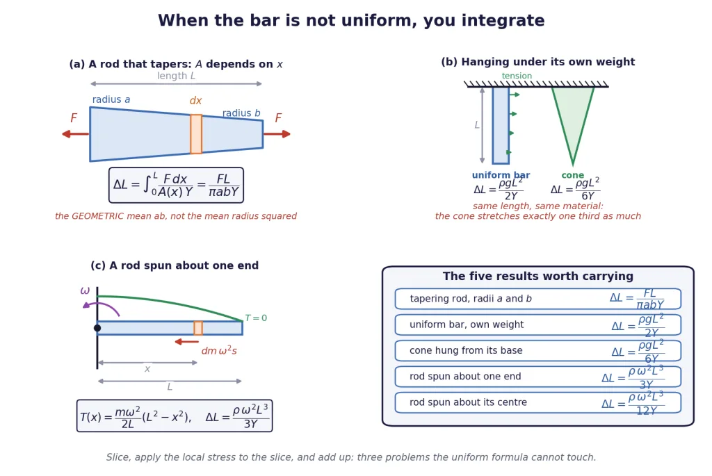
The method, in four lines
- Take an element of length at a distance from a stated end. It is short enough that the force and the area are constant across it.
- Write the force across that element, and the area of that element. This is the only step where thinking is required.
- Stretch the element: , which is applied to a bar of length .
- Integrate from one end to the other.
Case 1: the area varies, the force does not
A rod tapering from radius to radius . Pulled by an axial force at both ends, so every section carries the same . Taking from the end of radius , the radius at is , so and
Look hard at that answer. The area doing the work is — the geometric mean of the two end areas, since — and not , the area of a uniform bar of the mean radius. Whenever the geometric mean is the smaller of the two, so the real bar always stretches more than that mean-radius bar. Put and the result collapses to , as any correct answer must.
A bar of rectangular section, constant thickness , width growing linearly from to :
A logarithm, because a linear width puts in the denominator to the first power rather than the second. Notice that the two tapering results look nothing alike — you cannot guess one from the other, and the examiner knows it.
Case 2: the force varies, the area does not
A uniform bar hanging under its own weight. Measure down from the support. The section at has to hold up everything below it, a length of bar:
where is the total weight. That second form is the memorable one: the elongation is what you would get by hanging half the bar's weight from the free end of a weightless bar. Not the whole weight — half of it, because the top of the bar carries everything and the bottom carries nothing.
A solid cone hung from its base, apex pointing down. Now both vary, and they very nearly cancel. Measure up from the apex; the radius there is , so the area is and the weight hanging below that section is the weight of the little cone of height , namely . The stress at is their quotient:
Exactly one third of the uniform bar's answer, and completely independent of how fat the cone is. Both facts are asked directly.
Case 3: a rod that is spinning
A rod of mass , length , area and density rotates in a horizontal plane about a vertical axis through one end, at angular speed . Gravity plays no part; what stretches the rod is that every element needs a centripetal force, and only the material closer to the axis can supply it.
The section at distance from the axis must supply the centripetal force for everything beyond it:
Read three things off it immediately:
- is largest at the axis, where it equals — the same as if the whole mass sat at the midpoint, which is exactly where the centre of mass is.
- is zero at the free tip. Nothing lies beyond it to be pulled round.
- The rod will break at the axis, not at the tip.
Integrating gives the elongation:
Spin the same rod about its centre instead and the same method gives at the middle and
one quarter of the about-an-end value. Half the length on each side, and the cube in does the rest.
The five results, collected
| Situation | Elongation |
|---|---|
| uniform bar, axial load | |
| rod tapering between radii and , axial load | |
| bar of thickness , width , axial load | |
| uniform bar under its own weight | |
| solid cone hung from its base | |
| rod spun about one end | |
| rod spun about its centre |
Key Point: In every one of these the stress is what varies from point to point, and the elongation is the running total of the local strain. If you can write correctly, the integration is ordinary school calculus. The marks are in step 2, not step 4.
[Exam Tip] Check every non-uniform result by collapsing it. Put in the taper and you must get . Put in the spinning rod and you must get zero. Set the cone's answer beside the bar's and the ratio must be exactly . A result that fails one of these checks is wrong, and you will find out in ten seconds rather than at the end of the paper.
Composite Wires and the Rigid Bar
A wire of Young's modulus , area and length obeys , which is Hooke's law for a spring with force constant
Once you have written that line, every wire-combination problem in this chapter becomes a spring problem, and you already know how springs combine.
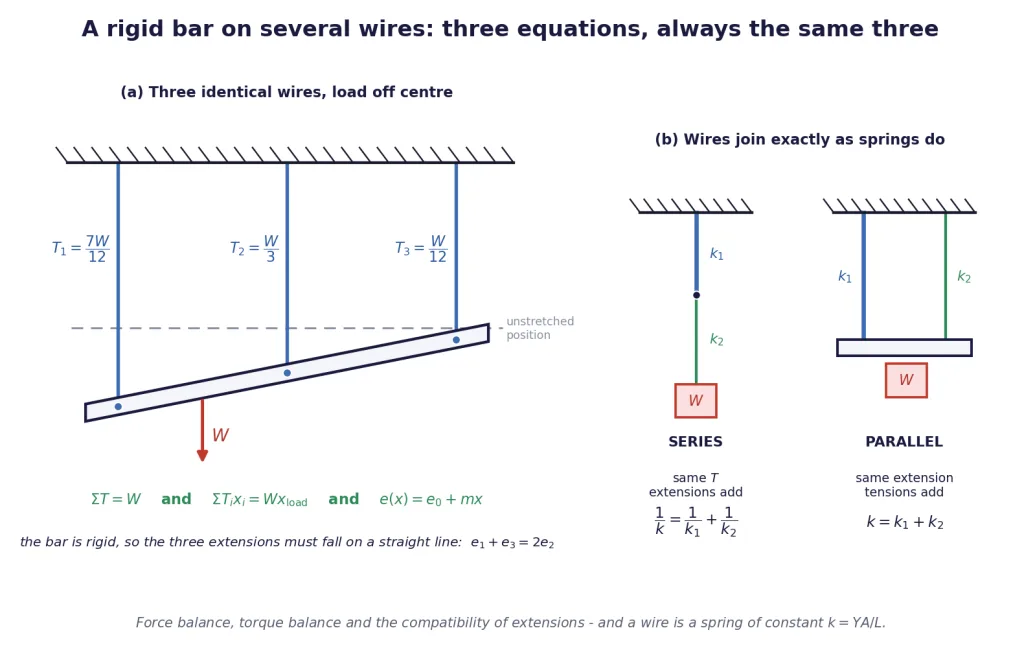
Series and parallel, in one table
| Series (end to end) | Parallel (side by side) | |
|---|---|---|
| what is shared | the tension | the extension |
| what adds | the extensions | the tensions |
| combination | ||
| the softer wire | stretches more | carries less load |
| stress | equal only if the areas are equal | equal only if the values are equal |
The two rows in bold are the whole thing. In series the same tension runs right through, so the wire with the smaller takes the bigger share of the stretch. In parallel everything is forced to stretch by the same amount, so the stiffer wire takes the bigger share of the load — load divides in the ratio of the values.
The rigid bar: three equations, always the same three
Here is the arrangement the paper actually sets. A light rigid bar hangs horizontally from two or more vertical wires, and a load is hung somewhere along it. Find the tensions.
You have more unknowns than the two equations of statics can supply, so you need a third relation, and it comes from geometry:
- Force balance. .
- Torque balance about any point on the bar. .
- Compatibility. The bar is rigid, so after everything has stretched it is still straight. The extensions of the wires, plotted against position along the bar, must lie on a straight line:
For two wires that third condition is just "the two ends are joined by a straight bar", which is automatic; two equations suffice. For three or more it bites, and it is what makes the problem solvable.
Key Point: For three equally spaced wires the compatibility condition has a form worth memorising: the middle extension is the average of the outer two. With identical wires that becomes directly.
Two wires, one horizontal rod — the classic
A light rod hangs from a wire at each end. Where must the load go?
The question has two different answers, and you must read which one is being asked.
- For the rod to stay horizontal, the two extensions must be equal:
- For the two wires to be under equal stress, the tensions must be in the ratio of the areas:
Then torque balance about one end converts a tension ratio into a distance. With the wires a distance apart and the load from wire 1, gives
Note the inversion: the load sits closer to the wire that carries the larger tension. Get that backwards and the answer is the reflection of the right one, which is exactly what the distractors are built from.
An honest warning about "equal strain"
"Equal extension" and "equal strain" are the same condition only when the wires have the same length. If the two wires are of different lengths, equal strain means , whereas a rigid horizontal bar demands . Read the wording, and if the problem says "the rod remains horizontal", it is the extensions that are equal, not the strains.
[Exam Tip] Whenever a problem gives you more wires than equations of statics, stop and count. Two wires: statics is enough. Three wires: you need compatibility, and the shortcut finishes it in one line. Four or more equally spaced: the extensions still lie on a straight line, so write with two unknowns, and solve force balance and torque balance for and .
Thermal Stress When Two Materials Share One Constraint
Section 9 established the single-material result: a rod clamped between rigid walls and heated through develops a stress
independent of both its length and its cross-section. JEE takes the next step and puts two different materials under one constraint, where neither the stress nor the strain is the same in the two of them.
Two rods end to end between rigid walls
A rod of material 1 (length , area , modulus , expansion coefficient ) is joined end to end with a rod of material 2, and the pair is clamped between walls that do not move. Heat the whole assembly through .
Step 1 — how much would they grow if free?
Step 2 — what force squeezes exactly that much back out? The rods are in series, so the same compressive force runs through both, and the two compressions add:
Step 3 — set them equal, because the total length is unchanged:
Two things follow at once, and both are examined.
- The force is the same in both rods, so if the areas are equal the stress is the same in both — even though the two materials are quite different. Series, not parallel.
- The strains are not equal. The junction between the two rods does not stay put: it moves, by measured from its original position. Compute it from either side and you must get the same answer with the opposite sign convention — a free check worth thirty seconds.
A rod inside a tube: the parallel version
Now weld a rod of material 1 along the axis of a tube of material 2, joining them only at the two end caps, and heat the pair. Nothing external holds them; they hold each other.
Both must finish at the same length, so if the tube wants to be longer, is prevented, and ends up in compression, while the rod is dragged out into tension. There are no external forces, so the two internal forces are equal and opposite, :
Notice how much simpler this is: only the difference of the expansion coefficients appears, and the lengths have cancelled entirely.
Key Point: Both problems are the same two-step idea — let it expand freely, then apply the force that restores the constraint. What differs is the constraint. Two rods between walls: the total length is fixed, the rods are in series, the force is shared. Rod inside a tube: the two lengths must be equal to each other, the members are in parallel, the forces are equal and opposite.
The bimetallic strip
Rivet two strips of different metals face to face, each of thickness , and heat them. The strip with the larger wants to be longer; it cannot slide, so the pair has no option but to bend, with the high- metal on the outside of the curve.
Let the assembly bend into an arc of radius measured to the interface, subtending an angle . The centre line of each strip sits a distance from the interface, so
Divide one by the other and use :
with the thickness of one strip. Three consequences, all of them tested:
- does not depend on the length of the strip. A longer strip curls through a bigger angle, not a tighter curve.
- : thin strips curl tightly. That is why a thermostat strip is thin.
- , so the curvature is proportional to the temperature rise. That linearity is precisely what makes the device a usable thermometer and switch.
For a strip clamped at one end, the free tip swings sideways by , which for a small angle is very nearly — and therefore grows as the square of the length.
This treatment ignores the elastic stresses the two strips exert on each other, which shift the neutral surface slightly; a full analysis brings the two Young's moduli in as well. For the ratios and the order of magnitude that objective questions want, the geometric result above is the one to use, and it is the one every paper expects.
[Exam Tip] In every thermal problem in this section, write the free expansion on one line and the elastic compression on the next, then equate. Do not try to write a single formula from memory — the composite results look similar enough to each other that recalling the wrong one is easy, while the two-step route cannot go wrong.
When the Load Is Moving: Lifts, Vertical Circles and a Dropped Mass
A wire does not know what is happening at the far end of it. All it feels is the tension, and its extension is whatever that tension came from. So every "elasticity meets dynamics" problem is really two problems bolted together: find the tension from Newton's laws, then feed it to the wire.
The easy half: tension from the motion
| Situation | Tension in the wire |
|---|---|
| mass hanging at rest | |
| lift accelerating up with | |
| lift accelerating down with | |
| lift in free fall | — the wire returns to its natural length |
| mass in a horizontal circle, wire nearly horizontal | |
| vertical circle, at the lowest point | |
| vertical circle, wire horizontal | |
| vertical circle, at the top |
For a stone that just completes a vertical circle, , and energy conservation gives . So
and since the extension is proportional to the tension, the wire at the bottom of the swing is stretched six times as far as it would be if the stone simply hung still. That factor of six is asked constantly, and it is the reason a rope that holds a static load can still snap when the load starts swinging.
A subtlety worth one line. In a horizontal circle the radius is , not , so strictly and must be solved together, giving . In every realistic case and the correction is invisible; quote the simple answer, and mention the exact one only if the question makes a point of it.
The hard half: a mass dropped instead of lowered
Now the classic. A wire hangs from a ceiling at its natural length. A mass is attached to the lower end and released from rest. How far does the wire stretch?
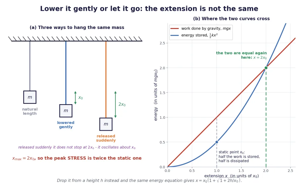
The wrong answer is , with . That is the extension you get if you lower the mass gently, supporting it all the way down until the wire alone can hold it. Released from rest, the mass arrives at moving, and keeps going.
Use energy. At the lowest point the mass is momentarily at rest, so all the work gravity has done has gone into the wire:
Key Point: A suddenly applied load produces twice the extension, and therefore twice the stress, of the same load applied gradually. A rope that is safe when a weight is lowered onto it can break when the same weight is dropped onto it from no height at all.
What actually happens next is simple harmonic motion: the mass oscillates about the static position with amplitude , so it runs between and . At the lowest point the wire pulls up with while gravity pulls down with , so the net force is upwards and the mass is thrown back. It stops permanently at only when damping has removed the energy.
And the missing half of the energy. Lower the mass gently through and gravity does of work while the wire stores only . The other half was not destroyed and did not go into the wire: your hand took it out, doing negative work as it let the mass down. Section 8 set this up; here is where it pays.
Dropped from a height
Let the mass fall a height before it starts stretching the wire. Gravity now does work over :
Two limits confirm it. Put and you get , the sudden-release answer. Let grow large and , which is just — all the fall energy stored in the wire, the drop dominating everything else.
The stress goes up in exactly the same ratio, and it goes up fast. Since is typically a fraction of a millimetre, dropping the load through even a few millimetres multiplies the peak stress by five or ten. This is why a crane is never allowed to let a load fall onto a slack cable, and why lifting slings are rated for "shock loads" separately.
Strain energy and what a fracture releases
The energy the wire holds is the area under its own force-extension line:
At the instant a cable snaps, all of that is released at once. A steel cable of length 20 m and cross-section 3.0 cm carrying a stress of Pa, with Pa, holds
Nearly four kilojoules, dumped in a few milliseconds, which is why a parting cable whips. Notice that the energy per cubic metre depends on the stress and the modulus alone — not on the length, not on the area. The length and area only decide how much material there is to hold it.
[Exam Tip] The single most expensive slip in this block is writing . The force grows from zero to as the wire stretches, so the work is the area of a triangle, not a rectangle, and the factor is not optional. If a question offers you both and among the options, that is the entire question.
Torsion in Depth
Section 5 introduced torsion: twisting is shear wrapped around an axis, the shearing angle at radius is , and the restoring couple is proportional to the twist. This block takes it as far as JEE goes.
The couple, built by integration
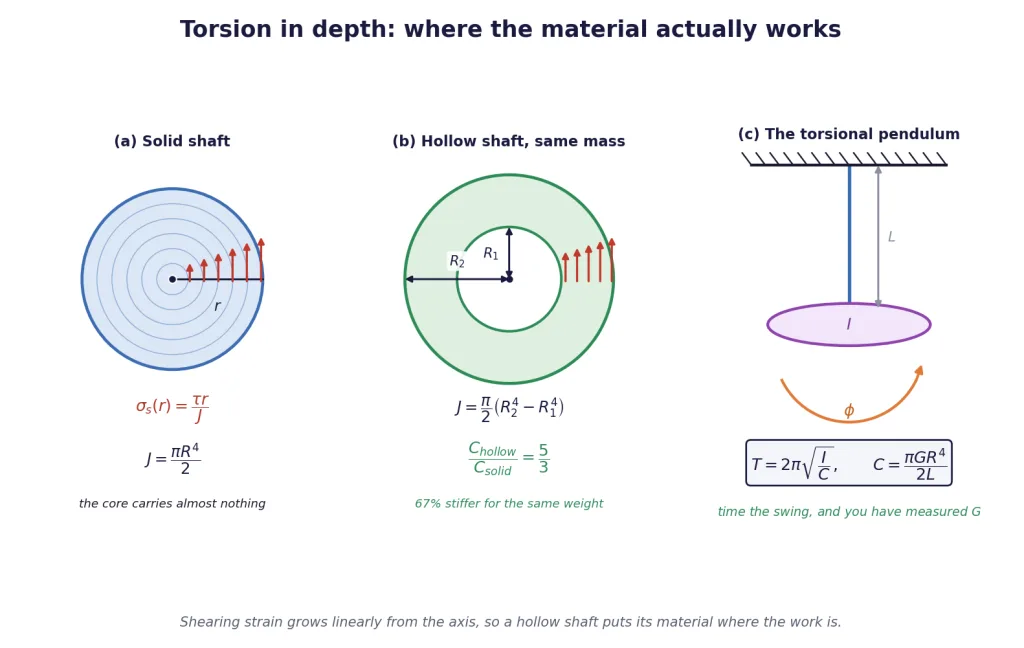
Take a thin annulus of radius and thickness in the cross-section of a shaft of length twisted through . Its shearing strain is , so it carries a shearing stress over an area . That force acts at a distance from the axis, so its moment is the stress times the area times :
Writing for the polar second moment of area of the section makes every result compact:
is the torsional rigidity — the couple per radian of twist, in N m per radian.
The stress distribution, and why hollow beats solid
The shearing stress at radius is
Linear in : zero on the axis, maximum at the surface. The material near the axis is barely working, yet it weighs just as much as the material near the rim. Remove it and you lose very little stiffness while losing a lot of weight.
Make the comparison properly. Take a hollow shaft of inner radius and outer radius , and a solid shaft of the same material, same length and same mass — so the same cross-sectional area, , giving . Then
Sixty-seven per cent stiffer for exactly the same weight, and it carries a given torque at a lower peak stress too. This is why drive shafts, bicycle frames, scaffolding poles and aircraft spars are tubes.
The is the headline
. Nothing else in this chapter is anywhere near as sensitive to a dimension.
| Change | Effect on | Effect on for a given couple |
|---|---|---|
| double the radius | ||
| double the length | ||
| 5% error in measuring | 22% error | 22% error |
| switch steel to copper ( halves) |
The torsional pendulum
Hang a body of moment of inertia from a wire of torsional rigidity and twist it. The restoring couple is , so
This is angular simple harmonic motion, the exact analogue of a mass on a spring with in place of and in place of . Two consequences:
- The period does not depend on the amplitude, provided the wire stays elastic.
- . Double the wire's radius and the period drops to a quarter of what it was.
Invert it and you have a laboratory method for measuring : time the oscillations, get , and then .
Energy, and combinations
Twisting stores energy exactly as stretching does, with playing the part of :
and the same factor of trap lies waiting. Wires combine in torsion exactly as springs do:
- In series (one hung below the other, the same couple through both): , and the twists add.
- In parallel (both attached to the same disc, both twisted by the same angle): , and the couples add.
Key Point: Torsion is governed by and never by , because twisting is shear. Any answer to a torsion problem containing is wrong unless the problem gave you and and expected you to get from first.
[Exam Tip] Most torsion questions are ratio questions in disguise. Write and , cancel everything the two cases share, and you are finished without ever evaluating or . Only reach for numbers when the question asks for an actual couple, period or stress.
The Four Constants, Used in Both Directions — and the Traps
Four constants, two independent
For a homogeneous isotropic solid there are only two independent elastic constants. Any two of , , and determine the other two, through relations that Section 7 derived:
JEE uses them in both directions, and the direction decides which one to pick.
| You are given | You want | Use |
|---|---|---|
| and | ||
| and | ||
| and | ||
| and | ||
| and | ||
| and |
Three limiting cases worth knowing cold
| If | then | meaning |
|---|---|---|
| and | volume exactly conserved: incompressible | |
| and , so , | the "Poisson solid", a common exam choice | |
| no lateral contraction at all (cork is close) |
The bounds are . A value above would make negative, meaning the solid expands when you squeeze it, and no ordinary material does that.
Being honest about real data
Test the relations on genuine tabulated values, taking , and from the same source for each metal and asking whether they actually fit:
| Metal | (Pa) | (Pa) | (Pa) | from | from | rebuilt from |
|---|---|---|---|---|---|---|
| Steel | , 7% high | |||||
| Copper | , 5% low | |||||
| Aluminium | , 4% low |
The relations tested on real tabulated moduli. Agreement is good, not perfect.
The two routes to disagree by five to seven hundredths, and rebuilt from and misses the tabulated by four to seven per cent. That is not an arithmetic error. Real metals are polycrystalline and not perfectly isotropic, the tabulated values are averages over different samples and different measurement techniques, and the relations assume a perfectly isotropic continuum. In an exam you use the relations as exact, because the question intends them to be; in a laboratory you would not expect better than five to ten per cent.
The four traps of this chapter, priced
1. The wrong area for shear. For longitudinal stress the area is the section perpendicular to the force. For shearing stress it is the face the force acts along — the face parallel to the force. A block m long, m deep and m tall, sheared along the top: the correct area is m, not the perpendicular section m. Using the second doubles the answer, and the error factor changes with the block's proportions, so you cannot recognise it from the size of the number. Name the loaded face in writing before you compute.
2. Forgetting the in the energy. The restoring force grows from zero to , so the work is . Both and will be among the options.
3. Treating breaking stress as if it depended on length. Breaking stress is a material property, measured in pascal, and a wire cut in half has exactly the same breaking stress and therefore carries exactly the same breaking load. What does depend on length is the maximum length a wire can hang under its own weight, — that is a different question with a different answer.
4. Reaching for the wrong modulus. Stretch or compress along one direction: . Slide or twist: . Squeeze from every side at once: . A twisted shaft never uses ; a wire under a hanging load never uses .
Key Point — the four sentences to carry out of this section:
- If the force or the area varies along the body, integrate; the master equation is .
- A wire is a spring with ; wires in series share the tension, wires in parallel share the extension.
- A rigid bar keeps its wires' extensions on a straight line — that is the third equation you were missing.
- A load dropped rather than lowered doubles the extension and doubles the stress.
[Exam Tip] In this chapter almost every wrong answer is one of five things: the wrong modulus, the wrong area, a missing , a radius used where a diameter was given, or an SI slip on mm ( mm m, not ). Before you commit an answer, run those five names down the margin. It takes eight seconds and it is the highest-yield habit in the whole chapter.
Solved Examples, Part 1: Integration and Compatibility
Values used in this section, unless a problem states otherwise: Pa, Pa, Pa, Pa, kg/m, m/s. Every constant is restated inside the solution that uses it.
Example 1: A rod that tapers along its length
A steel rod 1.0 m long tapers uniformly from a diameter of 20 mm at one end to 10 mm at the other. It is pulled by an axial force of 20 kN. Find its elongation, and compare it with what a uniform rod of the mean radius would give. Take Pa.
Solution:
Convert the diameters to radii, and be careful here — this is where half the marks are lost.
Set up the integral. The force is the same at every section (an axial pull), the area is not. At a distance from the thick end the radius is , so
Do the integral. The substitution turns it into , and it comes out as
Substitute.
The comparison. A uniform rod of the mean radius mm has m, giving
Final Answer: The tapered rod stretches m, that is 0.637 mm. The mean-radius estimate gives 0.566 mm. Measured against the exact value, as every error in this chapter is, that estimate is 11.1% low: . (Turned round the other way, the tapered rod stretches 12.5% more than the mean-radius rod — same two numbers, different denominator, so always say which one you divided by.)
Takeaway: is the geometric mean of the two end areas, and the geometric mean of two unequal numbers is always less than the arithmetic mean. So a real tapered bar always stretches more than the "average thickness" shortcut predicts, and the thinner end is doing far more than its share of the stretching.
Example 2: The bar whose width grows linearly
An aluminium bar 0.60 m long has a constant thickness of 10 mm, while its width increases uniformly from 20 mm at one end to 40 mm at the other. It carries an axial pull of 12 kN. Find its elongation. Take Pa.
Solution:
Area at distance from the narrow end, with m the thickness:
Integrate. With the area linear in rather than quadratic, the integral is a logarithm:
Substitute, with m and :
Sanity check against the mean width, 30 mm: m and m — only 3.8% below the exact value.
Final Answer: m, that is 0.357 mm.
Takeaway: Compare this with Example 1. Both bars taper, both are pulled axially — and the answers have completely different forms, one a simple product and one a logarithm, because a circular taper makes the area go as while a width taper makes it go as . You cannot guess a non-uniform result; you have to set the integral up. Notice also how much smaller the correction is here (3.8%) than there (11.1%): a linear area varies far more gently than a quadratic one.
Example 3: A cone hanging under its own weight
A solid steel cone of height 3.0 m hangs with its circular base fixed to a ceiling and its apex pointing straight down. Find the elongation produced by its own weight, and compare it with that of a uniform steel bar of the same length. Take kg/m, Pa, m/s.
Solution:
Measure up from the apex. If the base radius is , the radius at height is , so
The weight below that section is the weight of the little cone of height :
The stress at — and watch and cancel completely:
Integrate the strain:
Substitute:
The uniform bar of the same length gives m.
Final Answer: The cone stretches m, that is 0.573 micrometre — exactly one third of the uniform bar's m.
Takeaway: Two things fell out that a student never expects. First, the base radius cancelled: a fat cone and a thin cone of the same height stretch by the same amount. Second, the factor is exactly , and it comes from the in the volume of a cone. Both are asked directly, so it is worth carrying alongside .
Example 4: Spinning a rod about one end
A steel rod of length 1.2 m and uniform cross-section 4.0 mm is rotated in a horizontal plane about a vertical axis through one end, at 300 revolutions per minute. Find the maximum tension, the maximum stress, and the total elongation. Take kg/m and Pa.
Solution:
Angular speed and mass:
Tension at distance from the axis. The section there must supply the centripetal force for everything beyond it:
Maximum tension, at the axis where :
Maximum stress:
Elongation:
Final Answer: N at the axis, peak stress Pa, elongation m, that is 0.022 mm.
Takeaway: is the same as putting the whole mass at the midpoint — which is where the centre of mass is. That is a genuine shortcut for the maximum tension, and it is not a shortcut for the elongation, which needs the whole profile and gives , not . Spin the same rod about its centre instead and the elongation drops to one quarter of this.
Example 5: Three identical wires, and a load that is not in the middle
A light rigid horizontal bar hangs from three identical vertical steel wires attached at positions 0, 0.60 m and 1.20 m along it. Each wire is 2.0 m long with a cross-section of 1.0 mm and Pa. A load of 600 N is hung at 0.30 m from the first wire. Find the tension in each wire and the extension of each.
Solution:
The spring constant of each wire:
Count the unknowns. Three tensions, but only two equations of statics. The third relation is the rigidity of the bar: after stretching, it is still straight, so the extensions lie on a straight line, . Since the wires are identical, .
Force balance. , that is .
Torque balance about the first wire, with the load 0.30 m along:
Solve the pair. Eliminating gives with m, and then . Feeding those back:
Check both equations. Sum N. Torque N m. Both hold.
Extensions, from :
Final Answer: N, N, N, with extensions 3.5 mm, 2.0 mm and 0.5 mm.
Takeaway: Look at the three extensions: 3.5, 2.0, 0.5 — falling in equal steps of 1.5 mm. That is the compatibility condition made visible, , and it is the fastest way to check your own answer. Note also that the far wire is still in tension, not compression; if the load had been outside the wires, that would not have been true, and a wire cannot push.
Example 6: Where must the load hang for the rod to stay horizontal?
A light rigid rod 1.0 m long hangs horizontally from a steel wire at one end and a copper wire at the other. Both wires are 2.0 m long; the steel wire has a cross-section of 1.0 mm and the copper wire 2.0 mm. Take Pa and Pa. Where must a load be hung (a) for the rod to stay horizontal, and (b) for the two wires to be under equal stress?
Solution:
(a) Horizontal — equal extensions.
The spring constants are
Equal extensions means the tensions are in the ratio of the spring constants:
Torque balance about the steel end, with the load from the steel wire:
(b) Equal stress.
Equal stress means , so the tensions are in the ratio of the areas, .
Torque balance again:
Final Answer: (a) 0.545 m from the steel wire; (b) 0.667 m from the steel wire. Two different places.
Takeaway: Two conditions, two answers, and 12 cm between them. "Stays horizontal" is about extensions; "equal stress" is about areas. The examiner will phrase one of them and offer the other among the options, every time. Note the inversion in the torque step: the load sits nearer the wire carrying the larger tension, which is why and not the other way up.
Solved Examples, Part 2: Heat, Motion and Twist
Example 7: Two rods between two walls
A steel rod 0.30 m long is joined end to end with a copper rod 0.20 m long, both of cross-section 2.0 cm, and the pair is clamped between rigid walls at 20 °C. The assembly is heated to 120 °C. Find the force in the rods, the stress, and how far the junction moves. Take per degree, per degree, Pa, Pa.
Solution:
Step one — how much would the pair grow if it were free? With degrees and m:
Step two — what force squeezes that much back out? The rods are in series, so the same force acts in both, and the compressions add:
Step three — equate, because the walls do not move so the total length is unchanged:
Stress — the same in both rods, because the force and the area are the same:
Junction movement. The steel rod would have grown m but is compressed by m, so towards the copper side. Computing it from the copper end gives the same number, as it must.
Final Answer: N, stress Pa in both rods, and the junction shifts m (0.028 mm) into the copper.
Takeaway: The stress is common to the two rods (series, same force, same area) but the strain is not, and that is precisely why the junction moves. Students who assume the junction stays put lose the last part every time. Note also that Pa is uncomfortably close to the yield strength of mild steel — a real design would either allow a gap or use rollers.
Example 8: How tightly does a bimetallic strip curl?
A brass strip and a steel strip, each 0.20 mm thick and 10.0 cm long, are riveted face to face at 20 °C and then heated to 120 °C. Find the radius of curvature, the angle the strip turns through, and how far the free tip of the strip moves sideways if the other end is clamped. Take and per degree.
Solution:
Which metal ends up outside? Brass has the larger , so it wants to be longer and finishes on the outside of the curve. Good — that already rules out half of any option list.
The two arcs. With measured to the interface and each strip of thickness mm, the centre lines of the two strips sit at :
Divide and simplify, with :
The angle, from arc radius times angle:
The tip deflection. Exactly, it is m. The small-angle estimate m is 1% high.
Final Answer: m, the strip turns through rad (about ), and the tip moves about m, that is 1.7 cm.
Takeaway: Almost 2 cm of movement from a strip 10 cm long, for a temperature change any kitchen appliance sees — that is the whole reason bimetallic strips are used as switches. And note what does not depend on: the length. Make the strip twice as long and the radius is unchanged, but doubles and the tip deflection roughly quadruples, since it goes as .
Example 9: Dropping the mass instead of lowering it
A steel wire 2.0 m long with a cross-section of 1.0 mm hangs vertically ( Pa, m/s). Find the extension when a 2.0 kg mass is (a) lowered gently onto it, (b) attached at the wire's natural length and released from rest, and (c) dropped onto it from 5.0 mm above. Give the peak stress in each case.
Solution:
The wire as a spring:
(a) Lowered gently. The wire ends up carrying with the mass at rest:
(b) Released from rest. At the lowest point the mass is momentarily still, so all the work gravity has done is in the wire: and the stress is doubled too, Pa.
(c) Dropped from mm. Gravity now works over :
Energy check on (c). Stored J; gravity supplied J. They agree.
Final Answer: (a) 0.196 mm at Pa; (b) 0.392 mm at Pa; (c) 1.61 mm at Pa.
Takeaway: Read the last column. A 5 mm drop — the height of a fingernail — multiplied the stress by 8.2, and pushed a wire that was loafing along at Pa to within striking distance of yielding. Nothing about the load changed; only the way it arrived. This is what "shock loading" means, and why a crane operator never lets a load fall onto a slack cable.
Example 10: The same wire in a lift and in a vertical circle
A 10 kg block hangs from a steel wire 1.5 m long of cross-section 4.0 mm ( Pa, m/s). Find its extension when (a) the lift carrying it is at rest, (b) the lift accelerates upward at 2.0 m/s, (c) the lift accelerates downward at 2.0 m/s, (d) the lift cable snaps and it is in free fall. Then (e) the block is whirled in a vertical circle of radius 1.5 m at the minimum speed that completes the circle: find the extension at the lowest point.
Solution:
The spring constant: The wire never changes. Only the tension does.
(a) At rest. N, so m.
(b) Accelerating up. N, so m.
(c) Accelerating down. N, so m.
(d) Free fall. , so . The wire goes completely slack and returns to its natural length.
(e) The vertical circle. "Just completes" means the wire tension vanishes at the top, so , giving . Energy conservation from top to bottom, dropping :
Final Answer: (a) 0.184 mm, (b) 0.221 mm, (c) 0.146 mm, (d) zero, (e) 1.10 mm — six times the static value.
Takeaway: Every part used the same two lines: find the tension, then divide by . The wire's , and never entered the dynamics at all. And note the range: from zero in free fall to six times the static extension at the bottom of a vertical circle. A cable specified only for the weight it holds is under-specified.
Example 11: A hollow shaft against a solid one of the same weight
A hollow steel shaft has an inner radius of 20 mm and an outer radius of 40 mm. It is to be compared with a solid steel shaft of the same length and the same mass. Find (a) the radius of the solid shaft, (b) the ratio of their torsional rigidities, and (c) the maximum shearing stress in each when both carry a torque of 5.0 kN m. Both are 1.0 m long, with Pa.
Solution:
(a) Same mass and same length means the same cross-sectional area:
(b) Torsional rigidities. With :
(c) Peak shearing stress, which occurs at the outer surface, with … more directly, m and m:
Final Answer: (a) mm; (b) the hollow shaft is times stiffer; (c) Pa in the hollow shaft against Pa in the solid one — the solid shaft is worked 44% harder.
Takeaway: Same material, same length, same weight — and the tube wins on both counts, being 67% stiffer and running at a lower peak stress. The reason is the in : material near the axis is barely strained, so it contributes almost nothing to the couple while contributing its full share of the mass. Remove it, spread the rest further out, and every kilogram works harder.
Example 12: A torsional pendulum that measures
A uniform disc of mass 0.50 kg and radius 6.0 cm hangs horizontally from a vertical steel wire of length 1.0 m and radius 0.50 mm, attached at the disc's centre. Find (a) the torsional rigidity and the period of small torsional oscillations, taking Pa; (b) the value of that would be deduced if the period were measured as 2.10 s; (c) the energy stored when the disc is turned through .
Solution:
Moment of inertia of a disc about its own axis:
(a) Torsional rigidity, with the wire radius m:
(b) Working backwards from a measured period of 2.10 s: which is 2.3% below the accepted Pa.
(c) Energy at rad:
Final Answer: (a) N m/rad and s; (b) Pa; (c) J.
Takeaway: Part (b) is the whole reason this apparatus exists — a period you can time with a stopwatch delivers to a couple of per cent. But look where the sensitivity sits: , so a 1% error in measuring the wire's radius becomes a 4% error in , while a 1% error in the period becomes only a 2% error. Measure the wire's radius with a screw gauge, not a ruler — that single instruction is worth more than any amount of careful timing.