
What a Heat Engine Actually Is
Section 8 ended with a prohibition: no engine can turn heat wholly into work. This section is about what an engine can do, and how to compute it.
Strip away the pistons and turbines and every heat engine on earth has the same four parts.
Key Point — the anatomy of a heat engine:
- A working substance — the stuff that is actually heated, expanded and squeezed. Steam in a power station, a petrol-air mixture in a car, air in a jet.
- A source, a hot reservoir at temperature , from which the working substance draws heat each cycle.
- A sink, a cold reservoir at temperature , to which it rejects heat each cycle.
- A cycle — a sequence of processes that brings the working substance back to exactly the state it started in, so it can do it all again.
A reservoir is a body so large that heat can be drawn from it or dumped into it without changing its temperature. The sea, the atmosphere, a furnace fed continuously with fuel.
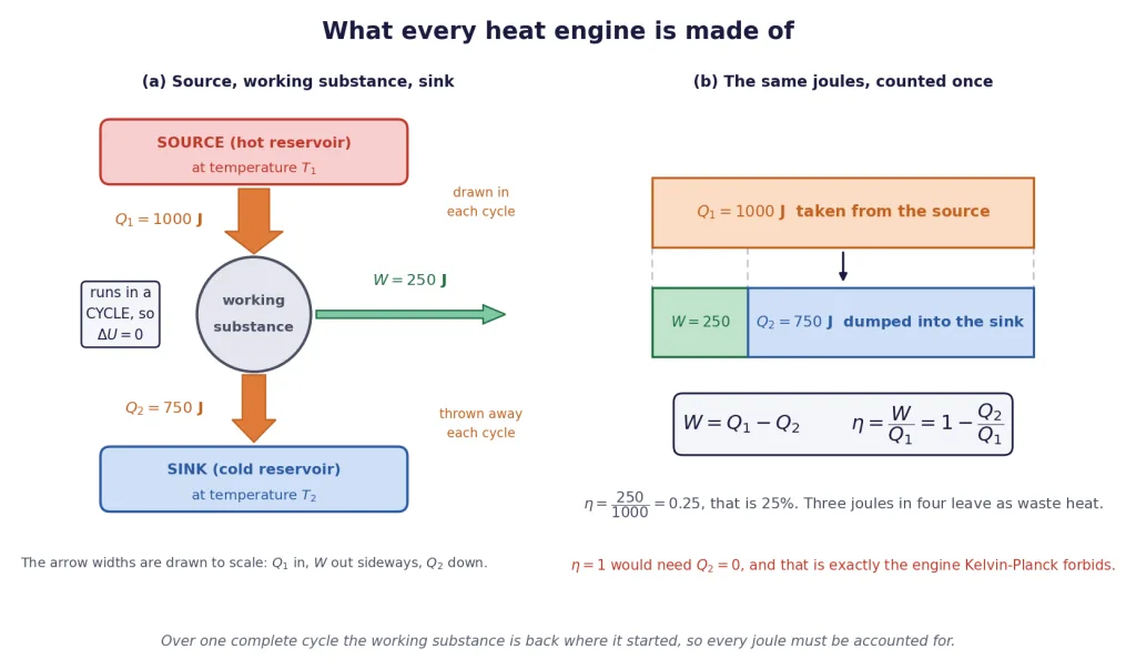
In that diagram, and everywhere in this chapter, the subscripts never move: and belong to the hot side, and to the cold side. is quoted as a magnitude, with its direction stated in words, so " J" always means 750 J rejected.
Where you meet the four parts in real machines
| Engine | Working substance | Source | Sink |
|---|---|---|---|
| Steam power station | water and steam | furnace burning coal or gas | condenser cooled by river or sea water |
| Petrol engine | petrol-air mixture, then burnt gases | the burning charge itself, after the spark | the exhaust pipe and the atmosphere |
| Diesel engine | air, then burnt gases | the charge ignited by compression | the exhaust and the radiator |
| Jet engine | air drawn in at the front | the combustion chamber | the atmosphere behind the aircraft |
Notice something about the petrol and jet engines: the working substance is thrown away at the end of each cycle and fresh air is drawn in. Strictly, those are open-cycle engines, and the "cycle" is completed by the atmosphere rather than inside the machine. For calculation this makes no difference at all — the atmosphere returns air at its original state, so the accounting is identical, which is why every textbook treats them as cyclic.
Why an engine is not just a gas expanding
A gas in a cylinder expanding once does work. So does a firework. Neither is an engine, because neither can do it again without being reset by hand.
An engine is a machine that repeats. That single requirement is what makes the whole subject non-trivial, and the next block shows exactly what it costs.
Why It Must Run in a Cycle, and What the Cycle Costs
Here is the argument that turns the second law into an equation, and it is three lines long.
The cycle forces
Internal energy is a state function — it depends only on the state the working substance is in, not on how it got there. At the end of a complete cycle the working substance is back in exactly its initial state: same pressure, same volume, same temperature. So its internal energy is back to exactly its initial value, and
not approximately, not on average, but exactly, for every cycle of every engine ever built.
Which forces the energy ledger to close
Feed that into the first law, , summed round the whole cycle:
The net heat absorbed over the cycle equals the net work done. Now split the heat into the part taken in and the part thrown out. Writing for the total heat absorbed and for the total heat rejected, both as positive magnitudes,
and therefore
Key Point — the engine equation: The work an engine delivers per cycle is exactly the difference between the heat it takes from the source and the heat it dumps in the sink. Every joule is accounted for; nothing is stored anywhere, because the working substance ends where it began.
That equation is not a model or an approximation. It is the first law plus the fact that is a state function, and it holds for a steam turbine, a scooter engine and a laboratory cycle drawn on graph paper alike.
Why the sink cannot be abolished
Now put the second law next to it. Kelvin-Planck forbids an engine whose sole result is drawing heat from a reservoir and converting all of it into work. A cyclic engine leaves nothing else changed — that is exactly what "cyclic" guarantees — so if it had no sink, its sole result would be complete conversion. Therefore:
Key Point: Every heat engine must have a sink, and must reject heat to it every cycle. is not merely hard to arrange; it is forbidden.
This is worth pausing on, because it is the point students most often refuse to believe. The rejected heat is not a design flaw waiting for a cleverer engineer. It is the price of being allowed to repeat.
[Board Important] "Why must a heat engine work in a cycle?" is a standard question. The full-mark answer has two halves: (i) so that the working substance returns to its initial state and the machine can operate continuously; (ii) because over a cycle, the work output is then exactly , with no energy hidden in the working substance.
Thermal Efficiency, and Why It Can Never Be One
The natural question about any machine is: what fraction of what I paid for did I get back?
Key Point — thermal efficiency: and since ,
is a pure number with no units. It is often quoted as a percentage; and "25% efficient" mean the same thing.
Note carefully what is in the denominator. It is , the heat drawn from the source — not the net heat, and not the heat rejected. You paid for the coal that went into the furnace, so is what you paid for.
Three forms of one formula
You will use all three, so keep all three:
| If you are given | Use |
|---|---|
| and | |
| and | |
| and one heat | , and |
And one more that saves time in rate problems: divide every term by the time taken, and the same relations hold between powers — (rate of heat input), and the rate of heat rejection is (rate of input) minus .
Why , in one line
Set in . You need : an engine that rejects nothing.
That is the perfect heat engine, and Section 8 showed it is precisely the machine the Kelvin-Planck statement forbids. So:
Key Point: is impossible, and is impossible, for every heat engine, of every design, using every working substance, for ever. Not because engineers are not clever enough — because the second law of thermodynamics says so.
Two related things follow, and both are examined:
- can never be negative either, for a machine that is genuinely an engine: if the net work came out negative the loop would be running the other way round and you would have a refrigerator, which is Section 10's business.
- has an upper bound far below 1, set by the two reservoir temperatures alone. The ceiling turns out to be with both temperatures in kelvin, and Section 11 derives it and proves nothing can beat it. This section quotes it only as a sanity check: if your answer for exceeds , you have made an arithmetic mistake.
Where the rejected heat actually goes
is not a bookkeeping fiction. You can go and put your hand near it. Follow 100 units of chemical energy through a car engine and this is roughly what becomes of them.
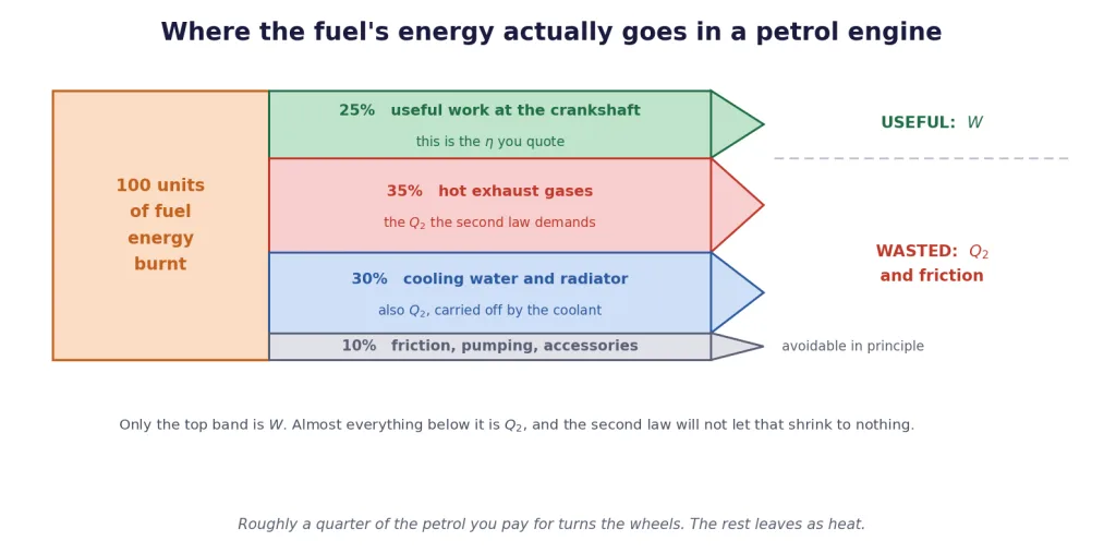
About a quarter reaches the crankshaft; the rest leaves as heat.
- In a coal or nuclear power station it goes into the condenser, and from there into a river, the sea, or those enormous cooling towers. A 500 MW station rejects roughly 800 MW of heat as warm water and vapour, day and night.
- In a car it leaves partly through the exhaust pipe as hot gas and partly through the radiator as warm coolant. That is why a car has a radiator at all: it is the sink, bolted to the front of the engine.
- In a jet it leaves as the hot exhaust behind the aircraft.
[NEET Important] A very common one-mark question: "Can the efficiency of a heat engine be 100%?" Answer: no — that would require , a perfect heat engine, which the Kelvin-Planck statement of the second law forbids. Say the reason, not just the word "no".
Reading an Engine Straight Off a - Diagram
Section 7 showed how to walk a cycle leg by leg and check that the columns sum correctly. An engine question asks for one more thing: which legs took heat in, and which threw heat out. Once you can separate those, costs you nothing.
Key Point — the method, five steps:
- Go round the loop leg by leg. For each leg compute , then , then . Keep the signs.
- Check the columns: must be exactly , and must equal . If they do not, stop and find the error.
- is the sum of the positive values only. is the sum of the magnitudes of the negative ones.
- , and it must equal the area enclosed by the loop. Two independent routes to the same number — use both.
- .
Step 3 is where marks are won and lost. is not the net heat. The net heat is . is the gross heat taken in, and it is always larger.
A useful shortcut for the ledger
For an ideal gas, , and , so
For a monatomic gas ; for a diatomic gas . So you can compute every straight from the corner coordinates without ever knowing or — which is fortunate, because most engine problems do not tell you either.
A worked cycle, in full
Take a monatomic ideal gas round the rectangle with L, kPa, L, kPa, L, kPa, L, kPa.
Useful conversion: 1 kPa L J J, so in kPa L is already in joules. Corner values: , , , J.
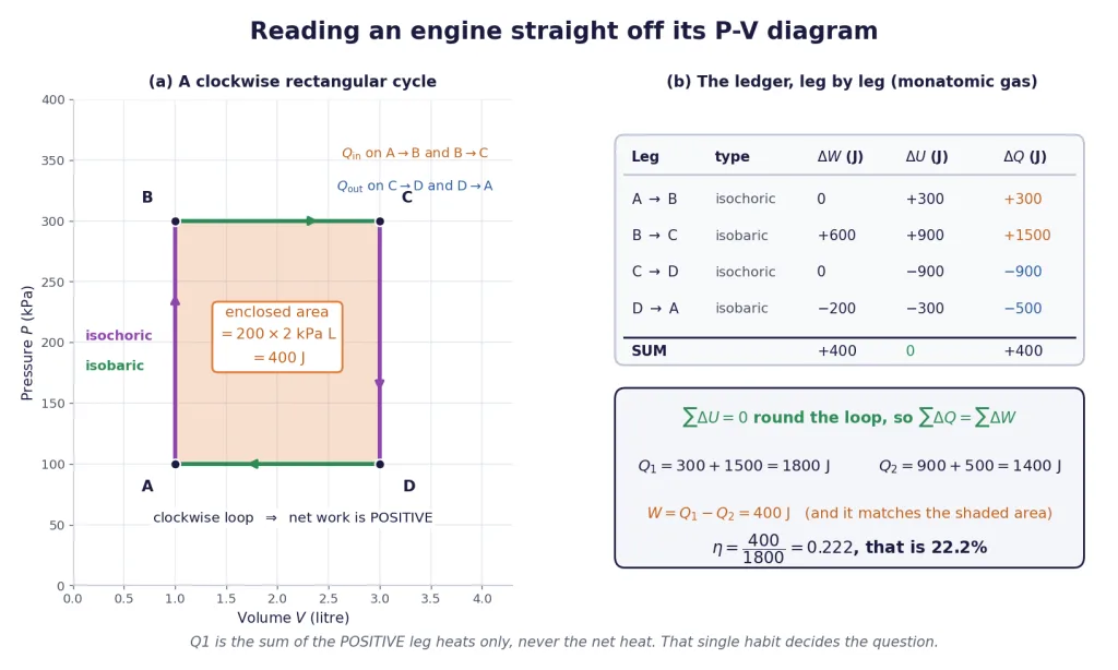
Leg , isochoric heating. Volume fixed, so . positive: heat in.
Leg , isobaric expansion at 300 kPa from 1 L to 3 L. Heat in.
Leg , isochoric cooling. . Negative: heat out.
Leg , isobaric compression at 100 kPa from 3 L to 1 L. Heat out.
The columns.
| Leg | (J) | (J) | (J) |
|---|---|---|---|
| in | |||
| in | |||
| out | |||
| out | |||
| Sum |
and J. The ledger closes.
The answer. which is exactly the enclosed area, J. And
Sanity check. The hottest corner is and the coldest is , and since , . (Here is the temperature at corner C of this cycle, not the sink temperature that some books write ; this chapter always calls the sink .) The ceiling is , and sits comfortably under it. Good.
One caution about sloping legs
On an isochor, isobar, isotherm or adiabat, the sign of is the same all the way along the leg, so "positive leg means heat in" is safe. On a straight sloping line it need not be: the gas can absorb heat over the first part of the leg and reject it over the rest, and the leg's net heat then hides a rejection. Example 6 works exactly that case, splits the leg, and shows how much the naive answer is out by. Class 11 cycles are almost always built from the four standard processes precisely so that this cannot bite.
Real Engines, and the Two Reasons They Fall Short
Everything so far has been ideal gases on graph paper. Here are the machines.
| Engine | Typical thermal efficiency |
|---|---|
| Early steam locomotive | about 8% |
| Modern coal or gas steam power station | 35 to 42% |
| Petrol (spark-ignition) car engine | 20 to 30% |
| Diesel engine, road or marine | 35 to 45% |
| Jet (gas turbine) engine in cruise | 30 to 40% |
| Combined-cycle gas power plant | 55 to 60% |
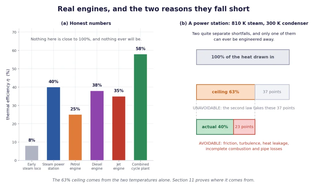
Nothing on that list is close to 100%, and the best entry on it took a century and a half of engineering to reach.
Where a tankful of petrol goes
Of the chemical energy in the petrol, about a quarter reaches the crankshaft. Around a third leaves down the exhaust pipe as hot gas, another third is carried off by the coolant into the radiator, and the last tenth is eaten by friction, pumping the gas in and out, and running the water pump and alternator. The flow diagram earlier in this section shows the split.
The two shortfalls, and only one of them can be fixed
This is the distinction the whole section has been building towards, and it is examined as a reasoning question rather than a numerical one.
Key Point — a real engine falls short for two quite separate reasons:
1. The unavoidable second-law limit. Even a perfect, frictionless, leak-free engine must reject heat to a sink. Its efficiency is capped at , with both temperatures in kelvin, and no design changes that. This shortfall cannot be engineered away, only pushed back by raising or lowering .
2. The avoidable practical losses. Friction in bearings and between piston and cylinder; turbulence and pressure drops in pipes and valves; heat leaking through walls that were meant to be adiabatic; combustion that does not quite finish; the pumps and fans the engine has to run for itself. Every one of these can be reduced by better engineering, and none of them can be reduced to zero.
Take a steam power station with steam at about 810 K and a condenser at about 300 K. The ceiling is and the station actually manages about 40%. So of the 60 percentage points it "loses", roughly 37 points are unavoidable and only about 23 points are the engineers' problem.
That is why power station design chases higher steam temperatures so hard: raising lifts the ceiling itself, while polishing the bearings only claws back a little of the second slice. And it is why a combined-cycle plant does so much better — it runs a gas turbine at a very high and then uses its exhaust to run a steam cycle underneath, effectively widening the temperature range the plant works over.
[JEE Tip] If a question gives you and and an engine's actual efficiency, it is almost always asking you to compare with . Two things to check instantly: the temperatures must be in kelvin, and the actual efficiency must be less than or equal to the ceiling. If the numbers say otherwise, re-read the question — an engine beating that ceiling is not a curiosity, it is an error.
Improving a real engine: what actually works
- Raise . Higher furnace or combustion temperatures raise the ceiling directly. Limited by what the metal will survive, which is why turbine blade alloys are such a serious field.
- Lower . Helps, but you cannot go below the temperature of the river or the air outside, so there is very little room here in practice.
- Reduce friction and turbulence. Real gains, but they only attack the second slice.
- Use the waste heat for something else. A power station that pipes its condenser heat into a district heating scheme has not raised at all — still counts only work — but it has stopped wasting . This is called cogeneration, and it is the most honest answer to "where does the rejected heat go?"
Solved Examples
Sign convention throughout: positive when heat is added to the working substance, positive when work is done by it, . and are quoted as positive magnitudes, with "absorbed" or "rejected" said in words.
Constants used unless a problem states otherwise: J/(mol K); for a monatomic gas and for a diatomic gas; specific heat capacity of water 4186 J/(kg K).
Example 1: The basic engine ledger
A heat engine absorbs 1000 J of heat from its source in each cycle and rejects 750 J to its sink. Find (a) the work done per cycle, (b) the efficiency, and (c) the change in internal energy of the working substance over one cycle.
Solution:
(c) first, because it is free. The working substance returns to its initial state at the end of a cycle and is a state function, so
(a) The work. With , the first law summed round the cycle gives : This is positive, so 250 J of work is done by the engine on its surroundings each cycle. Good — a clockwise, work-producing loop.
(b) The efficiency: Cross-check with the other form: . The two agree.
Read it back. For every four joules of coal burnt, one joule turns the shaft and three go up the chimney.
Final Answer: (a) J done by the engine; (b) ; (c) over the cycle.
Takeaway: Write first in every cycle problem. It is exact, it is free, and it is what makes legitimate.
Example 2: Working backwards from the efficiency
An engine of efficiency 30% delivers 3000 J of work per cycle. Find the heat absorbed from the source and the heat rejected to the sink in each cycle.
Solution:
Rearrange the definition. , so
Then the rejected heat, from :
Cross-check on the second form: which is the efficiency we started from, so the pair is consistent.
A note on the arithmetic. Use as the decimal 0.30, never as "30". Dividing by 30 instead of 0.30 is the most frequent slip in this whole topic and it is out by a factor of a hundred.
Final Answer: J absorbed; J rejected.
Takeaway: Efficiency questions are one division and one subtraction. Get from , then from , and check on .
Example 3: Power, heat rates and fuel
An engine of efficiency 25% delivers a steady mechanical power output of 5.0 kW. (a) At what rate does it draw heat from its source? (b) At what rate does it reject heat? (c) If it is fuelled by oil of calorific value J/kg, how much oil does it burn per hour?
Solution:
Rates obey the same relations as energies, because every term is divided by the same time. So
(b) The rejection rate is the difference: Three times the useful output, leaving as warm exhaust and warm coolant.
(c) Energy needed in one hour:
Final Answer: (a) 20 kW absorbed; (b) 15 kW rejected; (c) about 1.64 kg of oil per hour.
Takeaway: Never mix an energy with a rate. Decide at the start whether you are working in joules or watts, and if the question asks for fuel per hour, multiply by 3600 s at the very end.
Example 4: A rectangular engine cycle with a diatomic gas
A fixed mass of a diatomic ideal gas is taken round the cycle , where L, kPa, L, kPa, L, kPa, L, kPa. Find , , the net work and the efficiency.
Solution:
Set up the shortcut. For a diatomic gas , so . Working in kPa and litres makes come out directly in joules. Corner values:
, isochoric. ; J; J, absorbed.
, isobaric expansion. J, done by the gas; J; J, absorbed.
, isochoric. ; J; J, rejected.
, isobaric compression. J, done on the gas; J; J, rejected.
Check the columns.
| Leg | (J) | (J) | (J) |
|---|---|---|---|
| Sum |
and . The ledger closes.
Collect the heats. and the enclosed area is J. Two routes, one answer.
Efficiency:
Ceiling check. Hottest corner , coldest corner , and , so and the ceiling is . Our is far below it.
Final Answer: J absorbed, J rejected, J done by the gas, .
Takeaway: is 5700 J, not the net 900 J. Dividing the work by the net heat gives every single time, which should tell you immediately that you have used the wrong denominator.
Example 5: A cycle with two isothermal legs
One mole of a monatomic ideal gas is taken round the following cycle: isothermal expansion at 600 K from m to m; isochoric cooling to 300 K; isothermal compression at 300 K back to m; isochoric heating back to 600 K. Take J/(mol K). Find , , the net work and the efficiency. (This arrangement is the Stirling cycle, and real Stirling engines run on it.)
Solution:
Kelvin check. Both temperatures are already absolute: 600 K and 300 K, both positive. Every ratio below uses them as they stand.
, isothermal expansion at K. For an ideal gas on an isotherm, so
, isochoric cooling from 600 K to 300 K. No volume change, so :
, isothermal compression at K. Negative, so work is done on the gas, as compression demands. , so J, rejected.
, isochoric heating from 300 K to 600 K. ;
The columns.
| Leg | (J) | (J) | (J) |
|---|---|---|---|
| Sum |
Both checks pass: the internal-energy column sums to zero, and the heat and work columns agree.
Collect.
Ceiling check. The extreme temperatures are 600 K and 300 K, so the ceiling is . Our 24.0% is well inside it — which is exactly why a real Stirling engine is good but not miraculous.
Final Answer: J absorbed, J rejected, J done by the gas, .
Takeaway: The two isochoric legs cancel in the work column but NOT in the heat columns. absorbs 3741 J and rejects the same 3741 J, so they contribute nothing to and a great deal to — which is precisely what drags down to 24%.
Example 6: A triangular cycle, and the trap in a sloping leg
A monatomic ideal gas is taken clockwise round the triangle , where L, kPa, L, kPa and L, kPa, the leg being a straight line on the - diagram. Find the net work, and then find , and honestly.
Solution:
The net work is the enclosed area, and the triangle has base 2 L and height 200 kPa: Positive, because the loop runs clockwise.
The legs, in the usual way. With and , , J:
- , isochoric: , J, J.
- , sloping straight line: the work is the area of the trapezium under it, J. Both ends have J, so and the leg's net heat is J.
- , isobaric compression at 100 kPa: J, J, J.
Column sums: J; ; J. All three checks pass, and agrees with the area.
- Now the trap. It is tempting to write J and . That is wrong, and here is why.
Along the pressure falls linearly, with in kPa and in litres. Writing the heat absorbed per unit volume as and substituting gives a quantity that is positive up to L and negative after it. So the gas absorbs heat over the first three-quarters of that leg and rejects heat over the last quarter. The leg's net J is the difference of a J and a J.
The honest totals.
Ceiling check. Along , peaks at L with J, so the hottest state on the whole cycle is the middle of the sloping leg, not a corner. The coldest is , with J. Ceiling , and 26.7% is safely under it.
Final Answer: J; honestly, J and J, giving . The naive leg-by-leg reading gives 28.6% and is too high.
Takeaway: On a sloping leg, the sign of the heat can change part way along. The net work and the column checks are unaffected, but is not, so treat from a triangular cycle with care. On isochoric, isobaric, isothermal and adiabatic legs the sign is fixed and no such thing can happen.
Example 7: A power station, in megawatts
A thermal power station takes in heat at the rate of 800 MW and delivers 300 MW of electrical power. (a) Find its efficiency. (b) At what rate does it reject heat? (c) If that heat is carried away by cooling water whose temperature is allowed to rise by 10 K, what mass of water is needed per second? Take the specific heat capacity of water as 4186 J/(kg K).
Solution:
(a) The efficiency, using powers directly: A realistic number for a large steam station.
(b) The rejection rate: The station throws away two-thirds more than it sells.
(c) The cooling water. Each kilogram carries away J, and this is a temperature difference, so kelvin and Celsius give the same number here. Nearly twelve tonnes of water every second — which is why big power stations sit on rivers, coasts or under cooling towers.
Sanity check against the ceiling. With steam at about 810 K and a condenser at about 300 K the limit is , and . The number is physically possible.
Final Answer: (a) 37.5%; (b) 500 MW rejected; (c) about kg of water per second.
Takeaway: is a real river of warm water, not an accounting entry. Whenever a problem gives you a cooling flow, it is really asking you to compute first and then divide by .
Example 8: A petrol engine measured at the pump
A car engine burns petrol at 5.0 kg per hour and delivers 20 kW of mechanical power. The calorific value of petrol is J/kg. Find (a) the rate at which chemical energy is supplied, (b) the thermal efficiency, and (c) the rate at which energy is wasted as heat.
Solution:
(a) Convert the fuel rate to a power. 5.0 kg per hour is kg/s, so
(b) The efficiency: On the high side for a petrol engine, which is what you would expect from a manufacturer quoting its best operating point rather than city driving.
(c) The waste rate: Forty-one kilowatts of heat pouring out of the exhaust and the radiator — about the output of twenty domestic room heaters, which is exactly why a bonnet is hot.
Final Answer: (a) 61.1 kW; (b) ; (c) 41.1 kW wasted.
Takeaway: Calorific value mass rate gives you per second, and nothing else in the problem does. Convert kilograms per hour to kilograms per second before you multiply, not after.
Example 9: What an extra ten points of efficiency is worth
An engine takes in 2000 J per cycle. Its efficiency is improved from 25% to 35%. Find, for each case, the work per cycle and the heat rejected, and comment on where the gain came from.
Solution:
At 25%:
At 35%:
The comparison. The extra work per cycle is J — a 40% increase in useful output for a 10-percentage-point gain in efficiency. And the fuel bill has not changed at all, because is the same 2000 J.
Where did the 200 J come from? Straight out of , which fell from 1500 J to 1300 J. There is nowhere else it could have come from: the ledger has only three entries, and was held fixed.
Final Answer: At 25%: J, J. At 35%: J, J. The extra 200 J of work is heat that used to be rejected and now is not.
Takeaway: Improving an engine at fixed means, exactly, rejecting less. That is why the second law's floor under is a ceiling on — they are the same statement.
Example 10: From cycles per second to kilowatts
An engine absorbs 2000 J and rejects 1500 J in each cycle, and completes 5 cycles every second. Find (a) the work per cycle, (b) the efficiency, (c) the power output, and (d) the rate at which it consumes heat.
Solution:
(a) Per cycle, with :
(b) Efficiency: Efficiency is a ratio of energies per cycle, so the running speed does not enter it at all.
(c) Power output is work per cycle times cycles per second:
(d) Heat consumption rate: Check: , the same efficiency. Rates and per-cycle energies give identical ratios, which is a useful check on any answer of this type.
Final Answer: (a) 500 J; (b) 25%; (c) 2.5 kW; (d) 10 kW.
Takeaway: Efficiency does not depend on how fast the engine runs; power does. Doubling the speed doubles the power and leaves exactly where it was.
Example 11: Finding a missing leg from the sums
A four-stroke engine cycle has four legs. Three of them are known: the first absorbs 2400 J, the second rejects 1500 J, the fourth rejects 700 J. The net work per cycle is 500 J. Find the heat exchanged on the third leg, and hence , and .
Solution:
Use the cyclic condition. Round the loop , so J. Writing the unknown as : Positive, so the third leg absorbs 300 J.
Now sort the four legs into the two piles.
Check: J, which matches the given net work.
Efficiency:
Final Answer: The third leg absorbs 300 J; J, J, .
Takeaway: A missing leg is never really missing. round any cycle gives you one equation, and one equation is all you need for one unknown.
Example 12: How much of the shortfall is the engineers' fault?
A steam power station works between a boiler at 810 K and a condenser at 300 K, and achieves a thermal efficiency of 40%. (a) What is the highest efficiency any engine could have between these two temperatures? (b) Of the 60 percentage points the station "loses", how many are unavoidable and how many are in principle avoidable? (c) Is the quoted 40% physically possible?
Solution:
Kelvin check. Both temperatures are given as absolute values, 810 K and 300 K, and both are positive. A ratio of temperatures is about to be taken, so this matters.
(a) The ceiling. Section 11 proves that no engine between two reservoirs can beat This depends on the two temperatures and on absolutely nothing else — not the working substance, not the design, not the size of the plant.
(b) Split the shortfall. The station converts 40 of every 100 units. The first 37 points are the second law's, and no engineering will recover them. The remaining 23 belong to friction in the turbine bearings, turbulence and pressure drops in the pipework, heat leaking through lagging, and the pumps and fans the plant runs for itself.
(c) Is 40% possible? Yes: . Had the plant claimed 70%, the claim would be impossible, and the right response would be to reject the number rather than to look for a clever explanation.
Final Answer: (a) 63.0%; (b) 37.0 points unavoidable, 23.0 points avoidable; (c) yes, since .
Takeaway: Two separate shortfalls, and only one has an engineer's name on it. Raising attacks the first; reducing friction and leakage attacks the second. Knowing which is which is the whole point of this section.